This helps you quickly interpret patents by identifying the three key elements:
Problems solved by technology
Method used
Benefits of technology
Benefits of technology
[0012]It is an object of the invention to provide a droplet ejection apparatus that can carry out appropriate recovery processing easily and surely in the recovery processing for droplet ejection heads when the apparatus is powered on.
[0024]In the droplet ejection apparatus of the invention, it is preferable that the ejection failure detecting and recovery processing determining means selects the pump-suction process as the recovery processing for eliminating the cause of the ejection failure in the case where the ejection failure is not eliminated even by carrying out the flushing process by the flushing means predetermined times.
Problems solved by technology
However, in the apparatus that carries out the above-mentioned recovery operation automatically, for example, in the case where the apparatus is used in a manner to be powered on and off frequently and repeatedly, because a left time thereof becomes relatively short, it is often the case that the recovery operation is not carried out necessarily every power-on time.
In this case, there is a problem that ink is consumed necessarily.
However, there is a problem that the ink and the ink receptor are wasted.
Further, it is necessary for the user to have knowledge of the ejection failure, which lead to a problem that it is difficult to use the recording apparatus.
However, because it is easy for ink to thicken at low temperature and drying and to the contrary it is difficult for ink to thicken at high temperature and high humidity, the amount of discharged ink required to carry out the recovery processing in elapsed time varies greatly according to the conditions.
Thus, because there is the case that ink is discharged more than necessary, such an operation is wasteful.
Moreover, because clock means is necessary to carry out the conventional method, components of the apparatus are increased, and this causes the cost increases.
Method used
Image
Click on the blue label to locate the original text in one second.
Reading with bidirectional positioning of images and text.
Examples
first embodiment
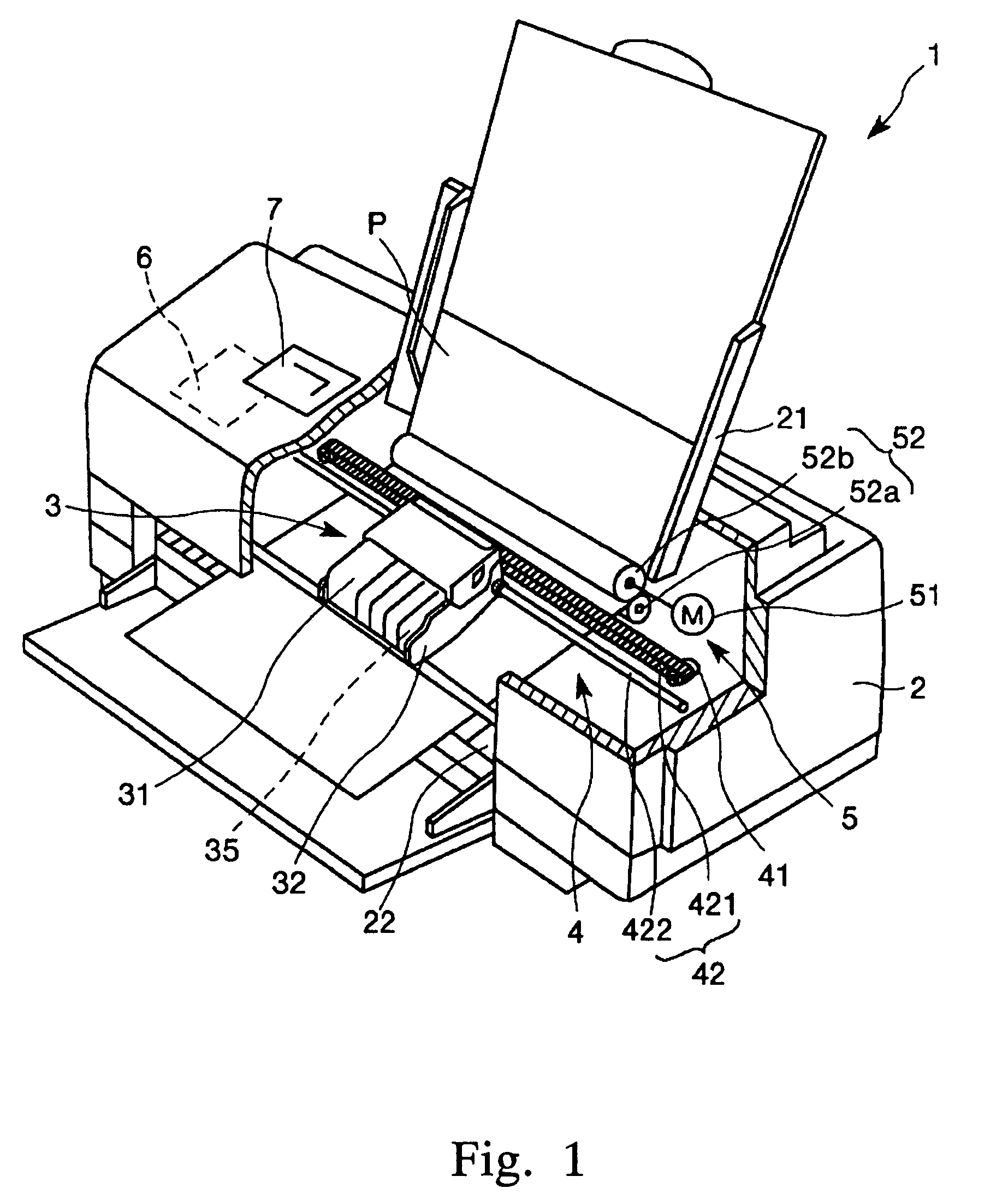
[0094]FIG. 1 is a schematic view showing the configuration of an ink jet printer 1 as one type of droplet ejection apparatus according to a first embodiment of the invention. Now, in following explanations using FIG. 1, an upper side and lower side are referred to as “upper” and “lower,” respectively.
[0095]Here, the main portion (feature) of the invention is the processing when the ink jet printer 1 is powered on. However, for ease of explanation, configuration and operation of the ink jet printer 1 will be described first, and then the processing when the ink jet printer 1 is powered on will be described.
[0096]The ink jet printer 1 shown in FIG. 1 includes a main body 2. A tray 21 on which recording sheets P may be placed, a sheet discharge port 22, through which the recording sheet P is discharged, and an operation panel 7 are respectively provided in the rear of the top, in the front of the bottom, and on the top surface, of the main body 2.
[0097]The operation panel 7 is provided...
second embodiment
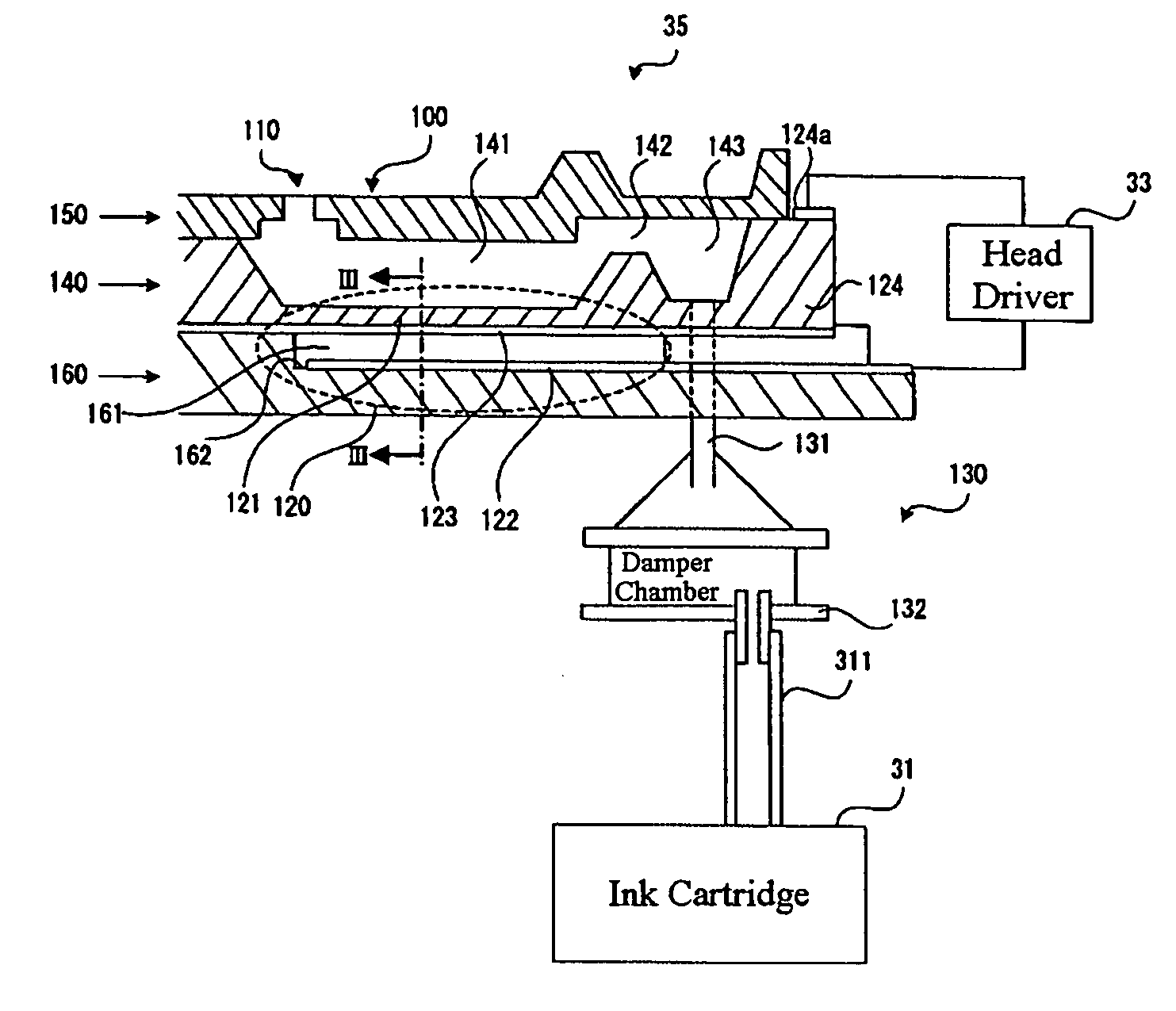
[0326]Examples of other configurations of the ink jet head of the invention will now be described. FIGS. 44-47 are cross sectional views each schematically showing an example of other configuration of the ink jet head (head unit). Hereinafter, an explanation will be given with reference to these drawings; however, differences from the first embodiment described above are chiefly described, and the description of the similar portions is omitted.
[0327]An ink jet head 100A shown in FIG. 44 is one that ejects ink (liquid material) within a cavity 208 through a nozzle 203 as a diaphragm 212 vibrates when a piezoelectric element 200 is driven. A metal plate 204 made of stainless steel is bonded to a nozzle plate 202 made of stainless steel in which the nozzle (hole) 203 is formed, via an adhesive film 205, and another metal plate 204 made of stainless steel is further bonded to the first-mentioned metal plate 204 via an adhesive film 205. Furthermore, a communication port forming plate 20...
third embodiment
[0342]An example of still another configuration of the ink jet head of the invention will now be described. FIG. 48 is a perspective view showing the configuration of a head unit 100H. FIG. 49 is a schematic cross sectional view of the head unit 100H corresponding to one color of ink (one cavity) shown in FIG. 48. Hereinafter, an explanation will be given with reference to these drawings; however, differences from the first embodiment described above will be chiefly described, and the description of the similar portions is omitted.
[0343]The head unit 100H shown in these drawings is a so-called film boiling type of ink jet head (thermal jet type), and is provided with a supporting plate 410, a substrate 420, an outer wall 430, partition walls 431, and a top plate 440, which are bonded to each other in this order from bottom to top of FIGS. 48 and 49.
[0344]The substrate 420 and the top plate 440 are placed so that they are spaced apart by a predetermined interval and the outer wall 43...
PUM
Abstract
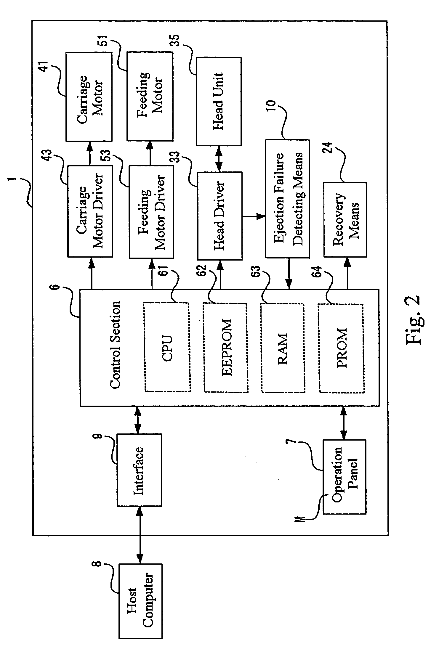
It is an object of the invention to provide a droplet ejection apparatus that can carry out appropriate recoveryprocessing easily and surely in the recoveryprocessing for droplet ejection heads when the apparatus is powered on. The droplet ejection apparatus of the invention has a driving circuit and a plurality of droplet ejection heads. Each of the droplet ejection heads includes a cavity filled with a liquid, a nozzle communicated with the cavity, an actuator driven by the driving circuit, and a diaphragm displaced by the actuator, and ejects the liquid within the cavity through the nozzle in the form of droplets by driving the actuator with the driving circuit. The droplet ejection apparatus further includes: ejection failure detecting and recoveryprocessing determining means (10) which detects a residual vibration of the diaphragm at least when the apparatus is powered on, and then detects an ejection failure of the droplet ejection heads on the basis of a vibration pattern of the detected residual vibration of the diaphragm and determines recovery processing for eliminating the ejection failure; and recovery means 24 for carrying out the recovery processing determined by the ejection failure detecting and recovery processing determining means.
Description
BACKGROUND OF THE INVENTION[0001]1. Technical Field[0002]The present invention relates to a droplet ejection apparatus.[0003]2. Background Art[0004]In an ink jet recording apparatus, which is one type of droplet ejection apparatus, when the apparatus has been left without carrying out a printing operation for a long time, a degree of ink viscosity in a recording head may be increased due to vaporization of a solvent in the ink (for example, water in the case of water-soluble ink) through ejection ports (nozzles) of the recording head (hereinafter, it is also referred to as “thickening ink”), or a relatively large bubble may occur in the ink due to intrusion of air on an ink supply system or growth of a minute air bubble that has been in the ink originally. Once such increase of the degree of ink viscosity or occurrence of the air bubble arises in an ink channel, which is communicated with the ejection hole of the recording head, or the like, the ejection operation of the recording h...
Claims
Application Information
Patent Timeline
Application Date:The date an application was filed.
Publication Date:The date a patent or application was officially published.
First Publication Date:The earliest publication date of a patent with the same application number.
Issue Date:Publication date of the patent grant document.
PCT Entry Date:The Entry date of PCT National Phase.
Estimated Expiry Date:The statutory expiry date of a patent right according to the Patent Law, and it is the longest term of protection that the patent right can achieve without the termination of the patent right due to other reasons(Term extension factor has been taken into account ).
Invalid Date:Actual expiry date is based on effective date or publication date of legal transaction data of invalid patent.

