Optical projector and image display apparatus using the same

a technology applied in the field of optical projector and image display device using the same, can solve the problems of affecting the image quality of the image, and increasing the intensity of interference, so as to achieve the effect of deteriorating image quality

Active Publication Date: 2007-08-28
MAXELL HLDG LTD
View PDF19 Cites 9 Cited by
  • Summary
  • Abstract
  • Description
  • Claims
  • Application Information

AI Technical Summary

Benefits of technology

[0005]Speckle noise occurs when light rays scattered by spatially separate minute diffusing elements interfere with each other at a point. In other words, since light emitted from an optional single point on the image generator passes two points on a screen and interfere with each other, the interference becomes more intense and the contrast of speckle noise becomes higher when the image generator is smaller and the surface density of outgoing light is greater; that is, the smaller the effective diameter D of the lens becomes, the higher the intensity of the interference is.
[0006]Accordingly, speckle noise can be reduced by increasing the effective screen size of the image generator or by using a lens having a large effective diameter D, which, however, runs counter to the trend toward using the image modulator as the image generator. Therefore, measures have been taken to avoid interference between light rays emitted from two points on the screen or to diffuse the interfering light rays into white noise by further diffusion.
[0007]A method of avoiding interference between light rays emitted from two points on the screen mentioned in Reference 2 forms a lenticular lens sheet included in a rear projection screen of a material not containing any diffusing material, and disposes a diffusing layer at distance longer than about three times the focal length of the lenticular lens from the lenticular lens sheet. Thus the lenticular lens increases the directions of light rays falling on the diffusing material and causing speckle noise to avoid interference. Although this method is effective in eliminating causes of speckle noise, the diffusing layer needs to be disposed at a distance longer than about three times the focal length of the lenticular lens from the lenticular lens sheet. Consequently, resolution is deteriorated greatly, which is a new problem.
[0009]Accordingly it is important to reduce speckle noise that is caused or liable to be caused in an image display apparatus by an image modulator as an image generator, and a projection lens having a large f-number included in the image display apparatus, suppressing the deterioration of resolution and contrast.
[0010]The present invention has been made in view of the foregoing problems and it is therefore an object of the present invention to provide techniques capable of satisfactorily suppressing the deterioration of image quality when an image modulator is used as an image generator.
[0017]According to the present invention, the deterioration of image quality due to, for example, speckle noise or the like can be suppressed when an image modulator is used.

Problems solved by technology

Speckle noise occurs when light rays scattered by spatially separate minute diffusing elements interfere with each other at a point.
In other words, since light emitted from an optional single point on the image generator passes two points on a screen and interfere with each other, the interference becomes more intense and the contrast of speckle noise becomes higher when the image generator is smaller and the surface density of outgoing light is greater; that is, the smaller the effective diameter D of the lens becomes, the higher the intensity of the interference is.
Consequently, resolution is deteriorated greatly, which is a new problem.
This method not only deteriorates resolution but also makes the second diffusing layer on the front side look white when external light falls thereon and decreases contrast in a bright place.

Method used


Image

  • Optical projector and image display apparatus using the same
  • Optical projector and image display apparatus using the same
  • Optical projector and image display apparatus using the same

Examples


first embodiment

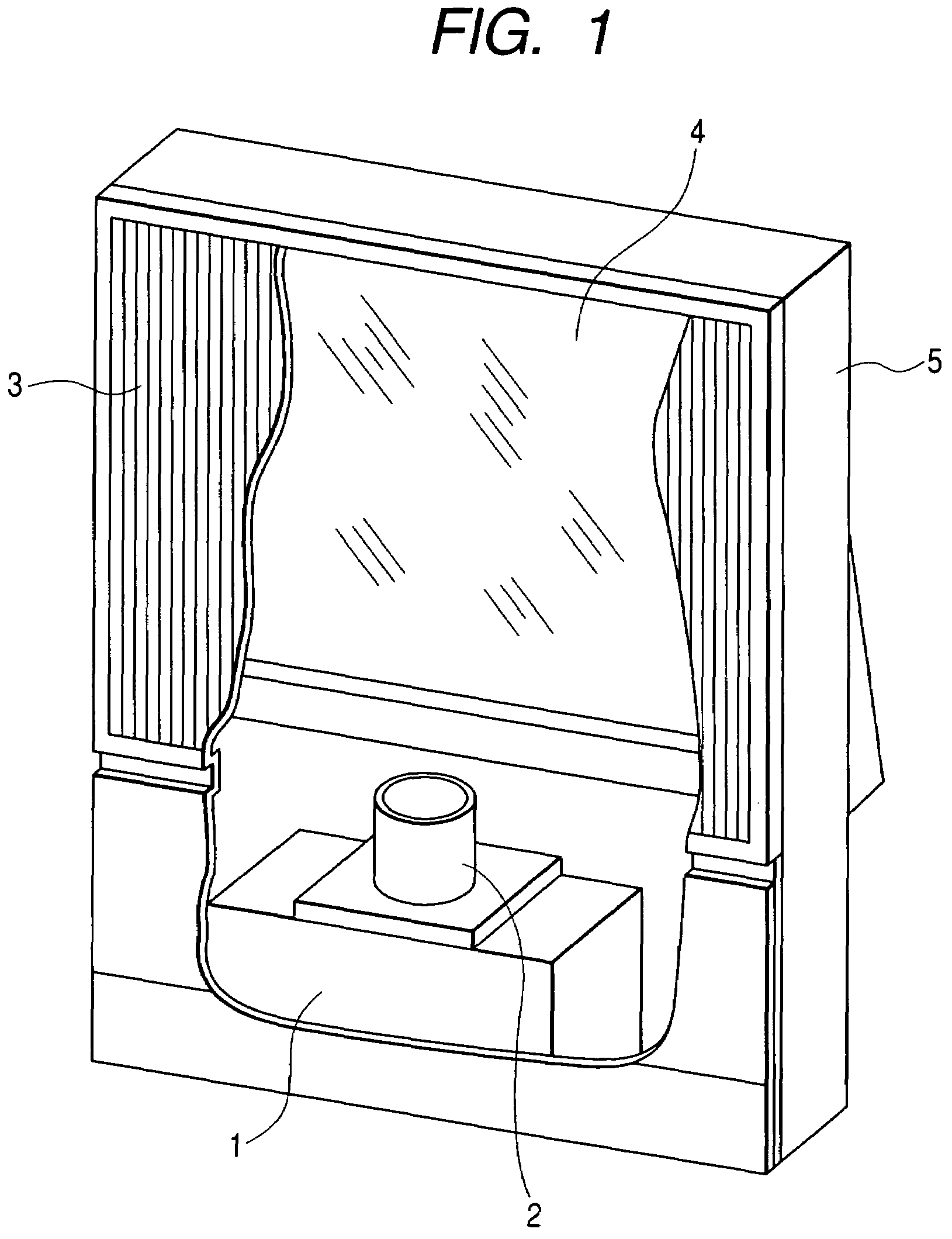
[0034]Referring to FIG. 1 showing an image display apparatus in a first embodiment according to the present invention is a partly cutaway perspective view, an image generator 1 includes a projection cathode-ray tube or a reflection or transmission liquid crystal panel, an image modulator, such as a mirror reflection optical modulator provided with a plurality of small mirrors, and an illuminating system including a lamp. The image generator 1 displays a small image. The small image is projected through a projection lens 2 on a rear projection screen 3. Generally, projection distance is long and hence a reflecting mirror 4 is disposed in an optical path between the projection lens 2 and the rear projection screen 3 to form the image display apparatus in a small longitudinal dimension. The image generator 1, the projection lens 2, the rear projection screen 3 and the reflecting mirror 4 are fixedly held at predetermined positions, respectively, in a cabinet 5.

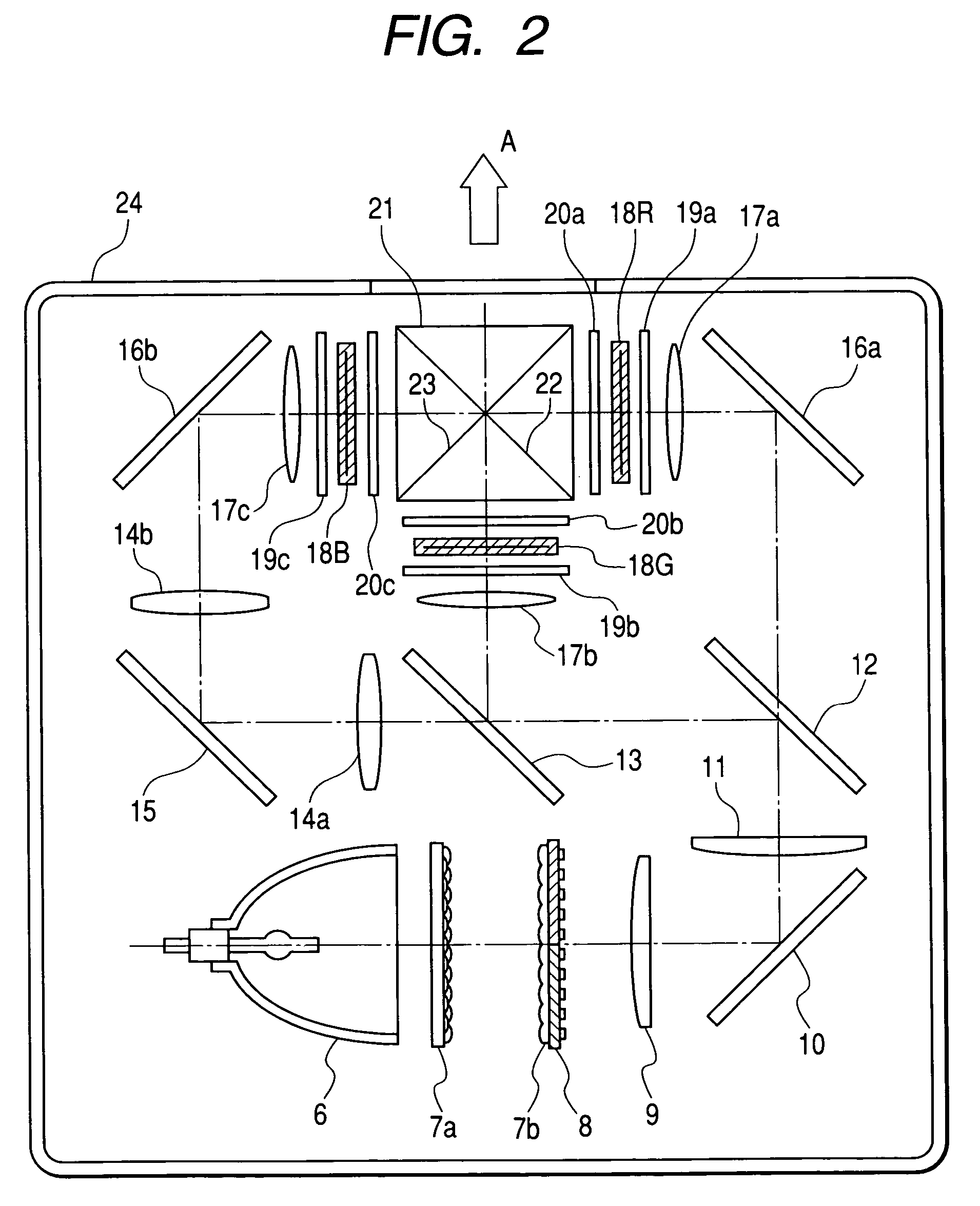
[0035]Referring to FIG. 2...

second embodiment

[0039]A unit included in an image generator in a second embodiment according to the present invention will be described with reference to FIG. 4, in which parts like or corresponding to those shown in FIG. 3 are denoted by the same reference characters. A liquid crystal panel 18 consists of a TFT substrate 25 and an opposite substrate 26, and is protected by an entrance dustproof glass plate 27 and an exit dustproof glass plate 28. The exit dustproof glass plate 28 has a haze value greater than that of the entrance dustproof glass plate 27, and serves as a scattering member for scattering image light. Generally, it is desirable that both the entrance and the exit dustproof glass plate have a high transmittance. However, if it is possible that speckle noise is generated, the exit dustproof glass plate 28 having a high haze value is used. Thus, speckle noise that appears on the rear projection screen 3 can be reduced by greatly scattering the light transmitted by the liquid crystal pa...

third embodiment

[0040]A unit included in an image generator in a third embodiment according to the present invention will be described with reference to FIG. 5, in which parts like or corresponding to those shown in FIG. 4 are denoted by the same reference characters. Generally, a liquid crystal panel 18 is a common part and hence, in some cases, it is difficult to form a special unit as shown in FIG. 4. In such a case, an exit dustproof glass plate 28 provided with a diffusive sheet 29 adhesively attached to the surface of the exit dustproof glass plate 28 may be employed. If the liquid crystal panel 18 needs cooling, the diffusive sheet 29 may be formed so as to have a necessary strength, and the diffusive sheet 29 may be interposed between the liquid crystal panel 18 and an exit polarizing plate 20.


PUM

PropertyMeasurementUnit
screen sizeaaaaaaaaaa
hazeaaaaaaaaaa
focal lengthaaaaaaaaaa

Abstract

Image disturbance called speckle noise occurs when an image generator has a small effective screen size and a projection lens has a small effective diameter. The present invention is intended to reduce speckle noise. In an optical projector, a viewing angle enlarging ember (60) for enlarging viewing angle or a scattering member (28) for scattering image light is disposed near an image display device (18), such as a liquid crystal panel. Speckle noise can be reduced, suppressing the deterioration of resolution and contrast.

Description

CLAIM OF PRIORITY[0001]The present application claims priority from Japanese applications serial no. P2003-421959, filed on Dec. 19, 2003, and serial no. P2004-132481, filed on Apr. 28, 2004, the contents of which are hereby incorporated by reference into this application.BACKGROUND OF THE INVENTION[0002]The present invention relates to an image display apparatus capable of enlarging and displaying an image produced by an image display device as an image generator on a screen by using optical parts including a projection lens, and an optical projector to be used in combination with the image display apparatus.[0003]Recently, the so-called pixel-selection type image modulators, such as liquid crystal panels, have become prevalently used instead of projection cathode-ray tubes as image generators for projection image display apparatus. The image modulator, for example, forms an image by modulating light emitted by a light source, such as a mercury lamp, for each pixel. The effective s...

Claims


Application Information

Patent Timeline
Patent Type & Authority Patents(United States)
IPC IPC(8): G03B21/14G02B5/00G02F1/13G02F1/01G02F1/1335G03B21/00
CPCG02B27/48G03B21/00G03B21/005
Inventor YOSHIKAWA, HIROKIOHISHI, TETSUHIRATA, KOJIIMAFUKU, DAISUKE
Owner MAXELL HLDG LTD
Why Eureka
Try Eureka