Method and apparatus for resource allocation based on buffer status information of neighboring cell
a resource allocation and neighboring cell technology, applied in the direction of transmission path sub-channel allocation, digital transmission, criteria allocation, etc., can solve the problem of inefficient resource use of scheduling methods, and achieve the effect of efficient resource allocation
- Summary
- Abstract
- Description
- Claims
- Application Information
AI Technical Summary
Benefits of technology
Problems solved by technology
Method used
Image
Examples
first embodiment
[0045]A case of partitioning and using a frequency resource is described as an example with reference to FIG. 5.
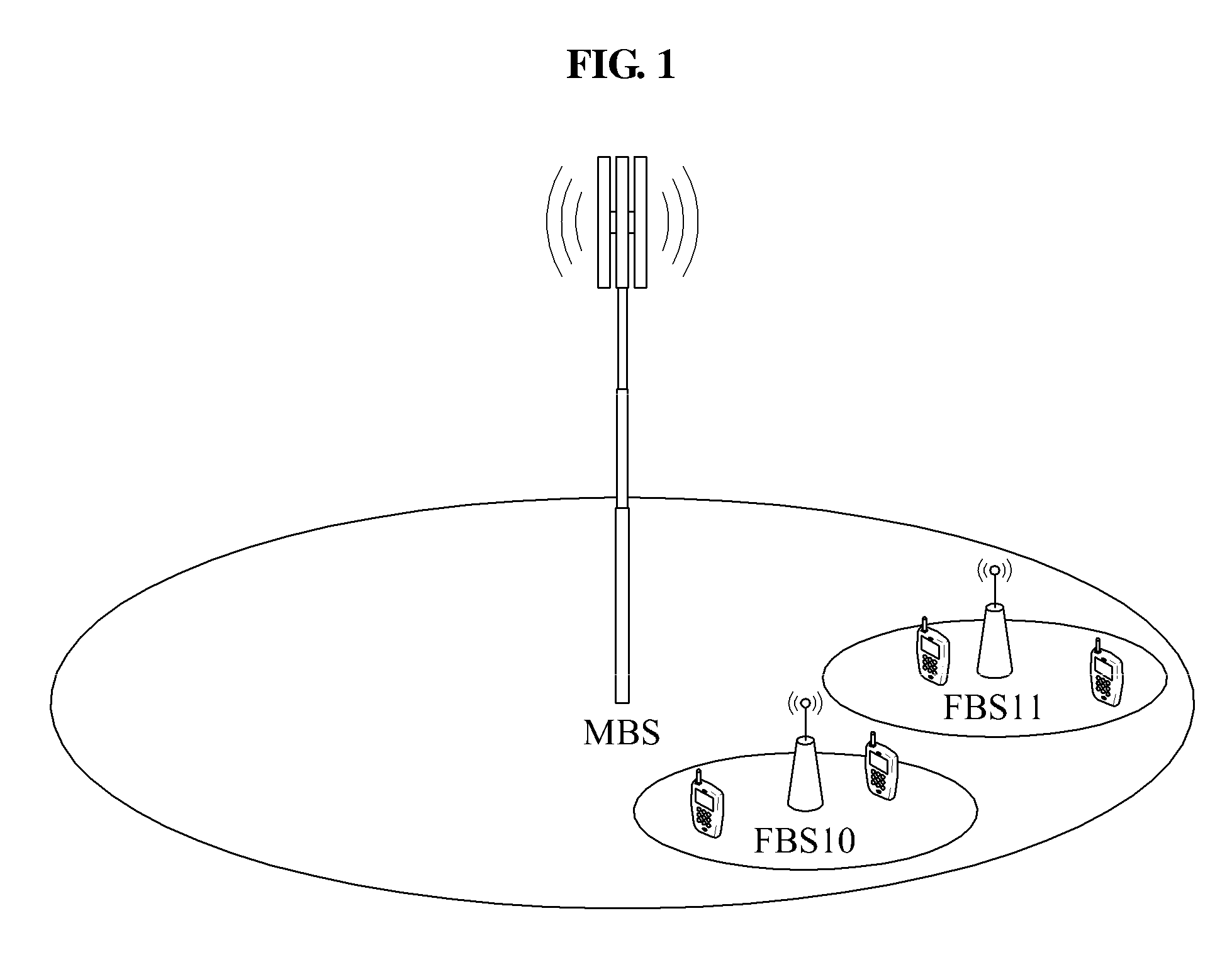
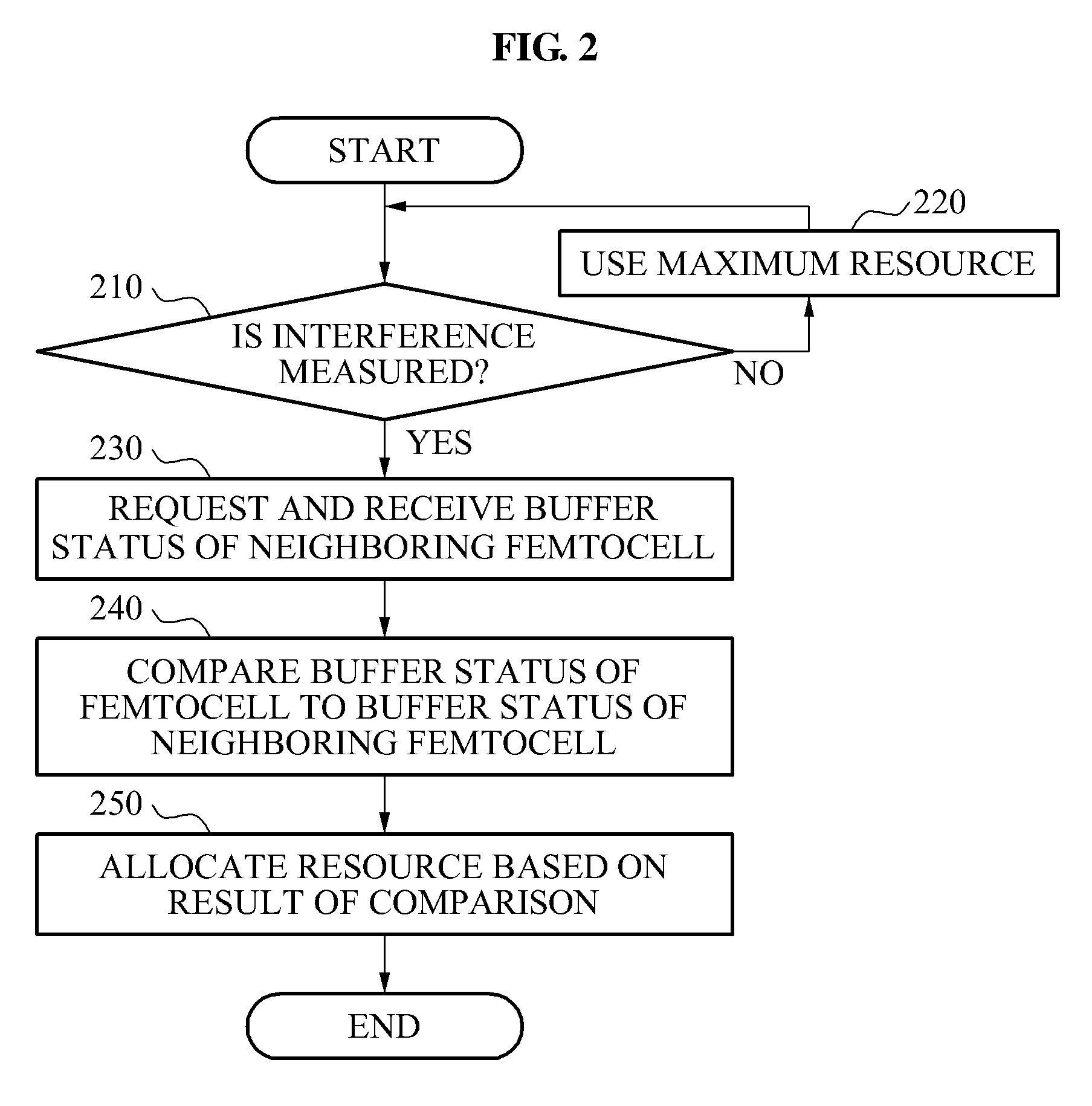
[0046]The first femtocell base station FBS10 may verify a buffer status of the first femtocell base station FBS10 and a buffer status of the neighboring femtocell base station FBS11, and when a resource required by the first femtocell base station FBS10 is greater than a resource required by the second femtocell base station FBS11 in an interference region, a resource greater than the resource of the second femtocell base station FBS11 among a shared resource between the first femtocell base station FBS10 and the second femtocell base station FBS11 may be used in an aspect of interference management.
[0047]For example, as shown in FIG. 4, a relatively larger amount of data may be accumulated in a buffer of the first femtocell base station FBS10 at an initial time t1, and as time t2 goes, a relatively larger amount of data may be accumulated in a buffer of the second femtoce...
second embodiment
[0049]A case of dividing and using a resource on a time axis is described as an example with reference to FIG. 6.
[0050]This may be designed to determine a signal transmission interval used for interference management based on the buffer status of the first femtocell base station FBS10 and the buffer status of the second femtocell base station FBS11 and to transmit a signal only for the determined interval, to prevent interference and achieve efficient resource allocation.
[0051]For example, as shown in FIG. 4, when an amount of data accumulated in the buffer of the first femtocell base station FBS10 is larger three times than that of the second femtocell base station FBS11 during t1, a signal transmission interval for the first femtocell base station FBS10 and a signal transmission interval for the second femtocell base station FBS11 may be allocated at 3:1 as shown in FIG. 6.
[0052]In contrast, a signal transmission interval allocated for the second femtocell base station FBS11 may b...
third embodiment
[0053]A case of adjusting a transmission power is described as an example with reference to FIG. 7.
[0054]As power of a signal transmitted from a base station increases, a delay caused due to hybrid automatic repeat request (HARM) retransmission may be reduced. Accordingly, the higher transmission power of the base station is, data accumulated in a buffer of the corresponding base station may be processed more quickly.
[0055]For example, when an amount of data accumulated in the buffer of the first femtocell base station FBS10 is larger three times than that of the second femtocell base station FBS11 during t1 as shown in FIG. 4, a transmission power level of the first femtocell base station FBS10 may be determined to be relatively higher than that of the second femtocell base station FBS11 as shown in FIG. 7.
[0056]In contrast, the transmission power of the second femtocell base station FBS11 may be relatively reduced and the transmission power of the first femtocell base station FBS1...
PUM
 Abstract
Description
Claims
Application Information
 - R&D
- Intellectual Property
- Life Sciences
- Materials
- Tech Scout
- Unparalleled Data Quality
- Higher Quality Content
- 60% Fewer Hallucinations
Browse by: Latest US Patents, China's latest patents, Technical Efficacy Thesaurus, Application Domain, Technology Topic, Popular Technical Reports.
© 2025 PatSnap. All rights reserved.Legal|Privacy policy|Modern Slavery Act Transparency Statement|Sitemap|About US| Contact US: help@patsnap.com


