Method for generating at least one backscattering zone of an ambient signal and/or for receiving a backscattered ambient signal

a technology of ambient signal and backscattered signal, which is applied in the field of generating at least one backscattered zone of ambient signal and/or receiving backscattered ambient signal, can solve the problems of deterioration of the execution of inconvenient decoding of backscattered signal, and insufficient interferen

Pending Publication Date: 2022-09-08
ORANGE SA (FR)
View PDF1 Cites 0 Cited by
  • Summary
  • Abstract
  • Description
  • Claims
  • Application Information

AI Technical Summary

Problems solved by technology

As a consequence, the distribution of power generated by this interference signal is not uniform and exhibits zones where the power is locally maximal or else inversely locally minimal.
The fact that the distribution of these zones is not controlled proves to be problematic in ensuring effective communication between the transmitter device and the receiver device which are traditionally arranged arbitrarily near each other.
In fact, if the receiver device is located in a locally maximal power zone, the level of interference can be sufficiently high

Method used


Image

  • Method for generating at least one backscattering zone of an ambient signal and/or for receiving a backscattered ambient signal
  • Method for generating at least one backscattering zone of an ambient signal and/or for receiving a backscattered ambient signal

Examples


first embodiment

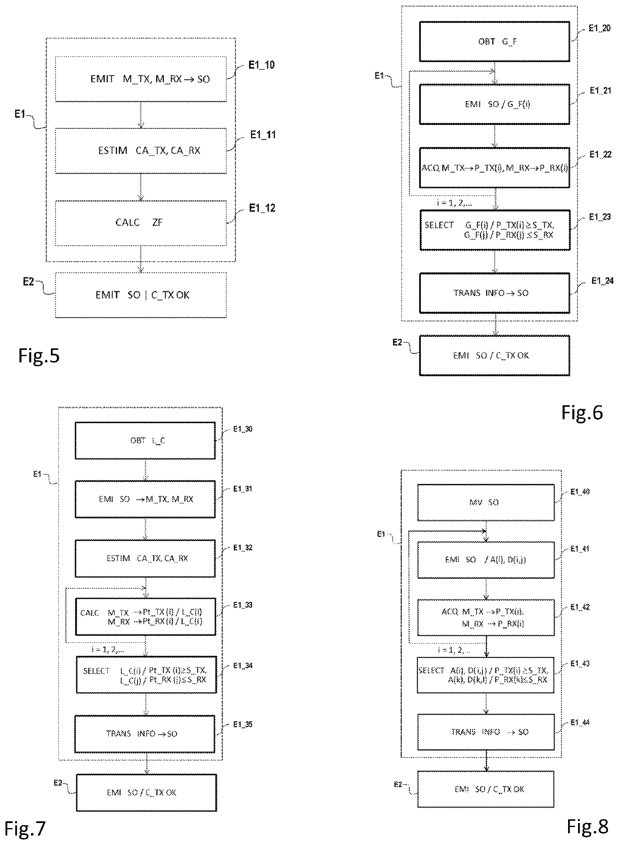
[0143]As illustrated by FIG. 5, step E1 for determining comprises, in this first embodiment, transmission E1_10, in the working band and by each of the terminals M_TX, M_RX, of at least one pilot sequence to the source SO.

[0144]The transmissions respectively associated with the first terminal M_TX and the second terminal M_RX are for example synchronised. Alternatively, these transmissions are desynchronised.

[0145]The determining Step E1 also comprises estimation E1_11, by the source SO and assuming channel reciprocity, of a propagation channel CA_TX, CA_RX between the source SO and each of the terminals M_TX, M_RX from the received pilot sequences.

[0146]The estimation of a propagation channel in a wireless network is a classic operation known to the skilled person, and consequently is not detailed here further. It is based especially on the sending of said sequences comprising pilot symbols on the propagation channel which are to be estimated. The assumption of reciprocity for esti...

second embodiment

[0156]As illustrated by FIG. 6, the determining step E1 comprises, in this second embodiment, obtaining E1_20, by the source SO, a grid G_F of beams (noted G_F(1), G_F(2), etc.) respectively associated with determined directions.

[0157]A direction of beam G_F(i) corresponds to a combination of directions of the space, such a combination can be shown algebraically in the form of a vectoral representation. Such a vector associated with a beam G_F(i) represents per se a precoder which, when utilised by the source SO for transmitting, focuses the transmission in the direction of the beam G_F(i) in question. Also, by adopting the abovementioned vectoral representation, the grid G_F of beams can be illustrated in the form of a matrix.

[0158]For example, the beams G_F(i) of the grid are determined by means of a method of Discrete Fourier Transform (“DFT”, for Discrete Fourier Transform). Such a method is for example described in the document: “DFT beamforming for more accurate estimate of si...

third embodiment

[0173]As illustrated by FIG. 7, determining step E1 comprises, in this third embodiment, obtaining E1_30, by the source SO as well as by each of the terminals M_TX, M_RX, a code book L_C (called “codebook”) comprising a plurality of precoders (noted LC(1), LC(2), etc.).

[0174]The fact of considering precoders LC(i) combined inside a code book L_C is well known to the skilled person who typically refers to a telecommunications standard to gain access to such a code book L_C. In this way, in the present exemplary embodiment (ambient signal of mobile telephony 4G), the code book L_C is supplied by a standard such as defined in the document: “3GPP TS 36.211 V15.5.0 (2019-03)”.

[0175]Said code book L_C is for example stored in annexed memory means of the source SO and terminals M_TX, M_RX, such as for example a database stored on a server. Since these annexed memory means are distinct from the memory means of the source SO and the terminals M_TX, M_RX, obtaining the code book L_C correspon...


PUM


Abstract

A process for generating at least one backscattering zone, by at least one transmitter device and to at least one receiver device, of an ambient radio signal emitted by at least one source; and a process for generating at least one reception zone, by the receiver device, of the backscattered ambient signal. The process for includes: determining an emission constraint, when it is respected by the source, for generating at least one backscattering zone in which the received electromagnetic power is greater than a determined threshold, called “backscattering threshold”, and/or generating at least one reception zone in which the received electromagnetic power is less than a determined threshold, called “reception threshold”; and transmitting, by the source, with respect to the emission constraint.

Description

PRIOR ART[0001]The present invention belongs to the general field of telecommunications. It relates more particularly to a process for generating at least one backscattering zone, by at least one transmitter device and to at least one receiver device, of an ambient radio signal emitted by at least one source, and / or for generating at least one reception zone, by said receiver device, of said backscattered ambient signal. It also relates to a communication process between at least one transmitter device and at least one receiver device, by backscattering an ambient radio signal emitted by at least one source. The invention applies application particularly advantageously, even though in no way limiting, for applications of the IOT” type (“Internet of Things”.[0002]The technology of ambient backscattering is well known today. The technical principles on which this technology is based are described especially in the document by N. Van Huynh et al. titled “Ambient Backscatter Communicati...

Claims


Application Information

Patent Timeline
IPC IPC(8): H04B7/06H04B7/08H04B5/00H04W52/38
CPCH04B7/0617H04B7/086H04B5/0031H04W52/38H04B7/15H04W52/42H04W52/46
Inventor FARA, ROMAINPHAN HUY, DINH THUY
Owner ORANGE SA (FR)
Why Eureka
Try Eureka