Clip feed arrangement

a feed arrangement and clip technology, applied in the field of clip feed arrangement, can solve the problems of undesirable stoppage times caused by the refilling operation of the magazine, limited suitability of the closure apparatus, and a large length restriction of the length and thus the capacity of the clip, so as to increase the output of the closure apparatus

Inactive Publication Date: 2008-02-19
POLY CLIP SYST
View PDF28 Cites 5 Cited by
  • Summary
  • Abstract
  • Description
  • Claims
  • Application Information

AI Technical Summary

Benefits of technology

[0010]Accordingly the object of the present invention is to provide a clip feed arrangement by which productivity and output of closure apparatuses can be increased.

Problems solved by technology

As the latter is arranged vertically by virtue of the drive action produced by the force of gravity and as it must be easily possible to reach the entry thereof for the purposes of manually drawing the lines of clips onto the magazine bar, its length and thus capacity are greatly restricted.
It is only limitedly suitable for closure apparatuses which operate at high speed as continuous manual restocking of the magazine would be required.
The stoppage times which are caused by that magazine refilling operation are undesirable.
At that point however the endeavors to increase productivity and output hit a limit as generally the clip reels have to be lifted manually onto the holder provided for mounting them, so that the weight thereof cannot be further unlimitedly increased.

Method used


Image

  • Clip feed arrangement
  • Clip feed arrangement
  • Clip feed arrangement

Examples


Embodiment Construction

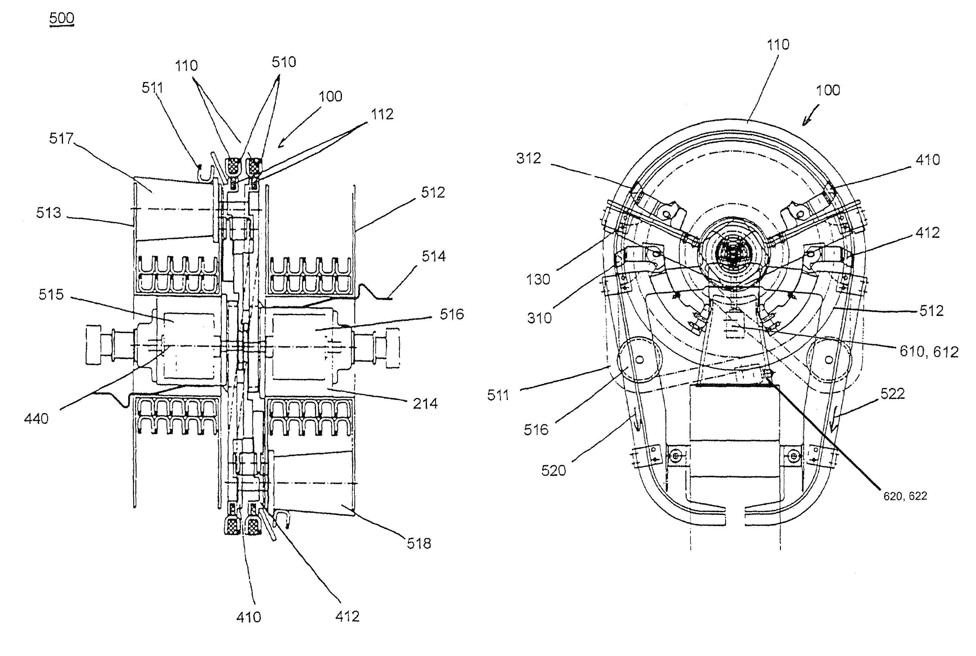
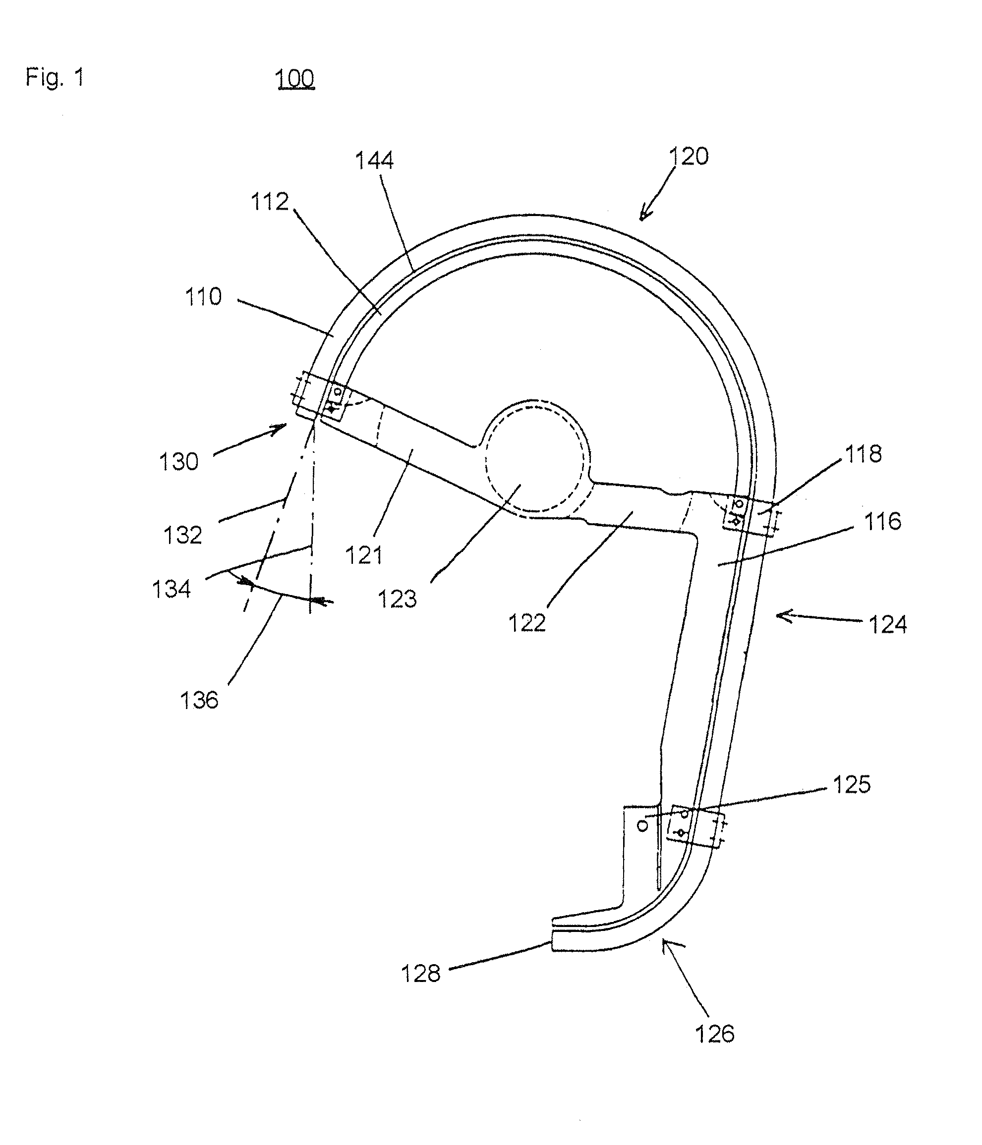
[0030]The magazine bar 100 according to the invention, as shown in FIG. 1, is composed of a plurality of structural elements. On the one hand it comprises an outer guide rail 110 whose cross-section, as shown in FIG. 5, substantially corresponds to the open cross-sectional profile of a U-shaped (pre-bent) closure clip 510 (referred to as the clip). Positioned in parallel relationship with the outer guide rail 110 is an inner guide rail 112 which, with the outer guide rail 110, defines a gap 114. The size of the gap approximately corresponds to the thickness of the wire of the clip so that the line of clips is securely guided between the two guide rails 110 and 112 in the manner shown in FIG. 5. The inner guide rail 112, on the side of the magazine bar 100 which is at the right as shown in FIG. 1, is functionally extended in a suspension means 116 which at the same time forms the central component for the entire magazine bar 100 in the manner described hereinafter. At the suspension ...


PUM

PropertyMeasurementUnit
flexibleaaaaaaaaaa
axial displacementaaaaaaaaaa
radiusaaaaaaaaaa

Abstract

A clip feed arrangement including a magazine bar for guiding a line of clips from a clip supply to a separating device of a closure apparatus, and a clip drive arranged in the region of the magazine bar. The clip drive has two drive elements which can be successively brought into engagement with the line of clips and which separately produce the advance.

Description

TECHNICAL FIELD[0001]The invention concerns a clip feed arrangement comprising a magazine bar for guiding a line of clips from a clip supply wound on a reel to a separating device of a closure apparatus for producing sausages and a clip drive arranged in the region of the magazine bar.BACKGROUND OF THE INVENTION[0002]The closure apparatus referred to hereinbefore is used for making sausages with a generally pasty filling material in a flexible tubular case (for example a sausage casing). Those closure apparatuses (also referred to hereinafter as automatic clipping machines) usually function in such a way that the filled tubular case which is closed at one end is constricted at a location by means of so-called displacement elements and thereupon filling material in the constriction region is displaced by a movement in the direction of the axis of the tubular case. At least one closure element (or clip) is placed on the plaited end portion of the tubular case which is formed in that w...

Claims


Application Information

Patent Timeline
Patent Type & Authority Patents(United States)
IPC IPC(8): B65B51/04A22C11/12B27F7/38
CPCA22C11/125Y10T29/53783
Inventor TOPFER, KLAUS
Owner POLY CLIP SYST
Why Eureka
Try Eureka