
Mail indication apparatus

a technology of mail indicators and apparatuses, which is applied in the field of improved mailboxes, can solve the problems of inconvenient installation of mail indicators, inability to meet the needs of customers, and inability to install flag signals, etc., and achieve the effect of low cost and easy installation without tools

Inactive Publication Date: 2008-02-19
BROWN LAWRENCE K
View PDF28 Cites 1 Cited by
  • Summary
  • Abstract
  • Description
  • Claims
  • Application Information

AI Technical Summary

Benefits of technology

[0025]It is a further object of this invention to provide a mail indicator that is easy to use.
[0035]It is a further object of this invention to provide a mail indication system which may be installed upon a user-determined area of the mailbox to allow a user to determine the best visibility position available for the signal flag.

Problems solved by technology

However the flag system as described may cause confusion over the meaning of the flag signals.
In addition, the device utilizes a complicated lever system which impairs to ease of installation within existing mail boxes.
However, the signal flag placed along the pivoting rod is not always visible from a distance as its connection to the rod allows the signal flag to rotate about the pivoting rod to an obscuring orientation.
The device does not contemplate the possibility of linkage entanglement, kinking, and linkage failure of the chaining mechanism, all of which would lead to failure of the device.
Further, the device utilizes a dual-door mail box, not commonly used.
The device is limited in its teachings as the signal rod extends vertically only when deployed, providing a limited surface facet for viewing by a mail recipient.
This device is limited in its efficiency as an alter system as it can be confused with the pop-up flag for posted mail.
The mounting of the assembly affects the integrity of the mail box by receptacle.
The device is limited in that it requires a bolt mounting for the device to the exterior of the mail box.
The mounting of the device affects the integrity of the mail box receptacle and additionally requires tools for the mounting.
This device is limited in its efficiency as an alert system as it can be confused with the pop-up flag for posted mail.
The mounting of the assembly affects the integrity of the mail box receptacle and additionally requires tools for the mounting.
This device is limited in its efficiency as an alert system as it can be confused with the pop-up flag for posted mail.
The mounting of the assembly affects the integrity of the mail box receptacle and additionally requires tools for the mounting.
The stem / flag assembly may be removed when absent to prevent an activated, non-attended flag posing a possible security problem.
However, the stiff, resilient stem utilized to maintain the flag in the upright position requires agile hands to reposition and refold the flag.
Some of the many drawbacks of mail indicators discussed above include complexity of the signal flag, interference for the mail postal person, mechanical unreliability of the signal flag, need for complex installation, loss of weather integrity of the mail box and signal flag positioning which limits a viewer's ability to identify when the signal flag has been deployed.
Unless the property owner actually catches the exact moment of arrival of the postal person, there is absolutely no way to determine that new mail has arrived.
Thus, it may be seen that these prior art patents are very limited in their teaching and utilization, and an improved mail indication system is needed to overcome these limitations.

Method used


Image

  • Mail indication apparatus
  • Mail indication apparatus
  • Mail indication apparatus

Examples


Embodiment Construction

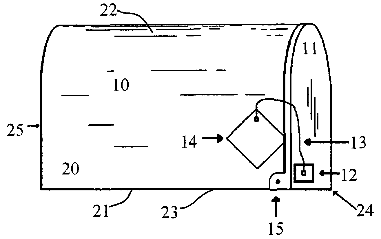
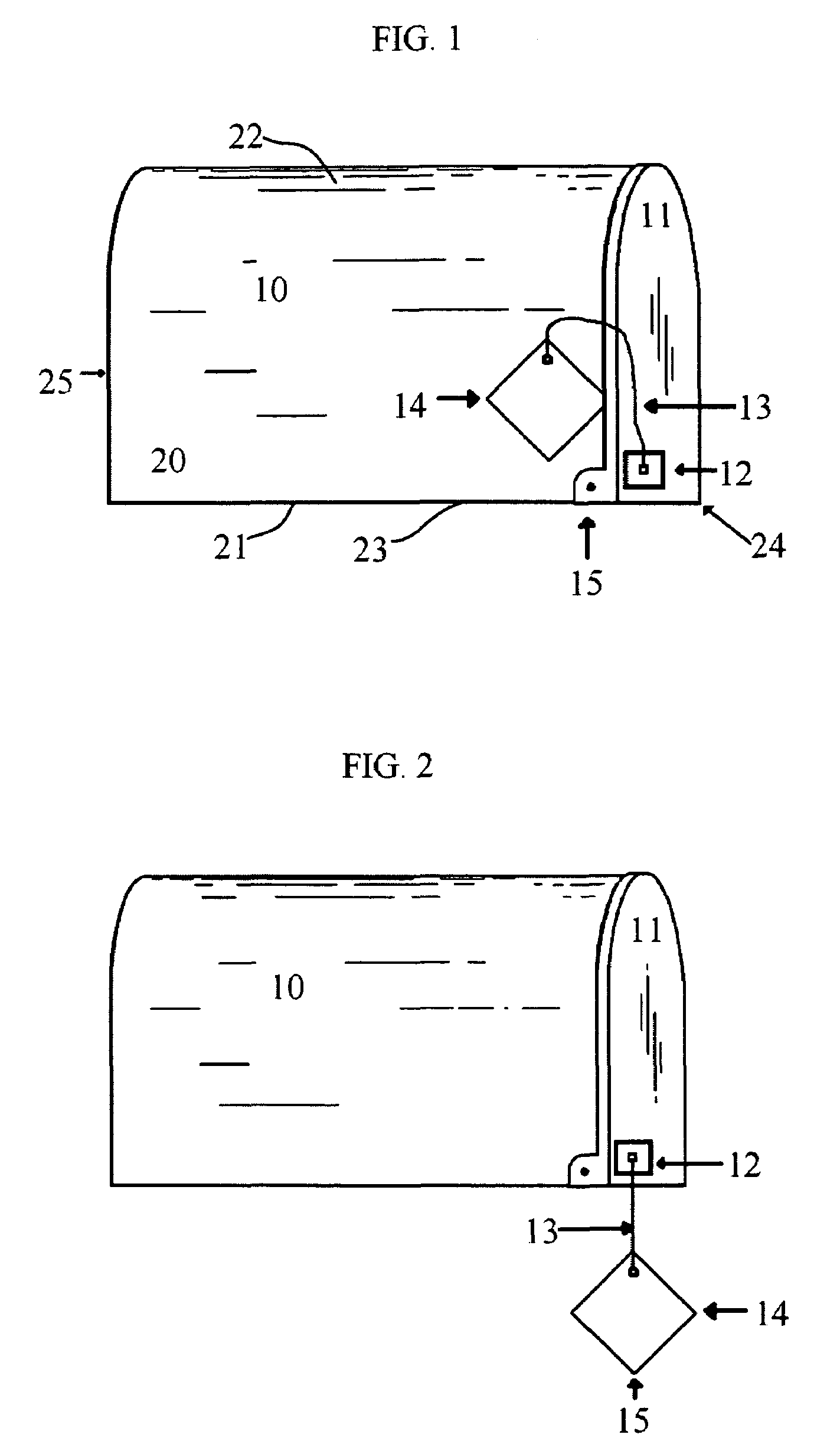
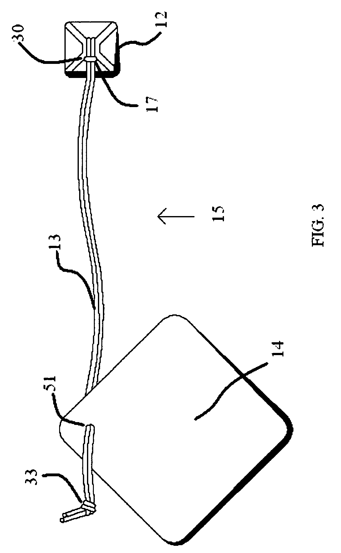
[0048]Generally speaking, the invention is directed to a mail indicating device 15 for determining whether the daily mail has arrived. The mail indicating device 15 includes a signal indicator 14, an attachment assembly 12, and a linking tether 13 connecting the signal indicator 14 to the attachment assembly 12. The signal indicator 14 is held wedged against the mailbox 10 and the movable opening 11 of the mailbox. Opening of the movable opening 11 for delivery of mail causes the signal indicator 14 to drop to an observable position below the mailbox, thus indicating that mail has been delivered. Upon retrieval of mail, the indicating device 15 is reset.

[0049]Now referring to FIG. 1, the mail indicating device 15 is shown in a first operative position with the signal indicator 14 held against the mailbox10. The mailbox 10 as shown includes an exterior shell 20 having a bottom 21, a curved top side 22 extending from the left side 23 of the bottom 21 to the right side 24 of the bottom...


PUM


Abstract

The invention features a mail indication device for determining whether the daily mail postal person has deposited mail in a rural or suburban mailbox. The mailbox indicator features a signal indicator composed of a dense material, a linking tether, and an attachment assembly mounted near or to the mailbox door.

Description

CROSS-REFERENCE TO RELATED APPLICATIONS[0001]This application claims priority to and is a continuation-in-part of U.S. provisional application Ser. No. 60 / 824,358, filed Sep. 1, 2006.STATEMENT REGARDING FEDERALLY SPONSORED RESEARCH OR DEVELOPMENT[0002]Not ApplicableREFERENCE TO A MICROFICHE APPENDIX[0003]Not ApplicableRESERVATION OF RIGHTS[0004]A portion of the disclosure of this patent document contains material which is subject to intellectual property rights such as but not limited to copyright, trademark, and / or trade dress protection. The owner has no objection to the facsimile reproduction by anyone of the patent document or the patent disclosure as it appears in the Patent and Trademark Office patent files or records but otherwise reserves all rights whatsoever.BACKGROUND OF THE INVENTION[0005]1. Field of the Invention[0006]The invention pertains to improvements in mailboxes, and more particularly to an improved mail indicator that notifies the mail recipient when the daily m...

Claims


Application Information

Patent Timeline
Patent Type & Authority Patents(United States)
IPC IPC(8): A47G29/12
CPCA47G29/121A47G2029/12105
Inventor BROWN, LAWRENCE K.
Owner BROWN LAWRENCE K
Learn More