Dog clutch and method for overdrive

Inactive Publication Date: 2008-02-19
GM GLOBAL TECH OPERATIONS LLC
View PDF16 Cites 20 Cited by
  • Summary
  • Abstract
  • Description
  • Claims
  • Application Information

AI Technical Summary

Benefits of technology

[0005]An electric motor, which is an electrical power unit for purposes of an electrically-variable transmission (EVT), is comprised of a rotor and a stator. By way of example, the stator of an electric motor may be rigidly mounted to the transmission housing and the rotor may be rigidly affixed to a sun gear, which may rotate about the transmission main shaft. When an engine is propelling an EVT vehicle, it may be desirable to lock up the sun gear to utilize discrete gear ratios. Thus, it is an object of the present invention to introduce a small and simple clutch that may ground a rotor hub and associated sun gear to a fixed body in a transmission, such as the transmission housing.
[0006]A hydraulically-actuatable clutch adapted for use in an EVT is provided. The clutch of the present invention may be utilized to ground the rotor and sun gear to the transmission housing in an EVT. The clutch has a piston which is always splined to the sun gear and the rotor hub and which is engageable with the transmission housing. At any time the piston may either be engaged with or disengaged from the transmission housing. When engaged, the clutch grounds the rotor and sun gear to the transmission housing such that the rotor and sun gear may not rotatably slip with respect to the transmission housing. When disengaged, the rotor and sun gear may rotate about the transmission main shaft, which may include or may be connected to the input member of the hybrid transmission.
[0009]The dog clutch of the present invention may be smaller than prior electrically variable transmission friction clutches that rotatably locked the sun gear and rotor to the transmission housing or cover. Additionally, the mechanics of the dog clutch of the present invention may be simpler than previously utilized friction clutches. Further, the hydraulic control utilized to actuate the dog clutch of this invention may potentially be simpler than a friction clutch for grounding the rotor, if controlled electrically, as by a solenoid.

Problems solved by technology

A dog clutch is a mechanical clutch that provides a solid lock when engaged and does not allow for any slipping.

Method used


Image

  • Dog clutch and method for overdrive
  • Dog clutch and method for overdrive
  • Dog clutch and method for overdrive

Examples


Embodiment Construction

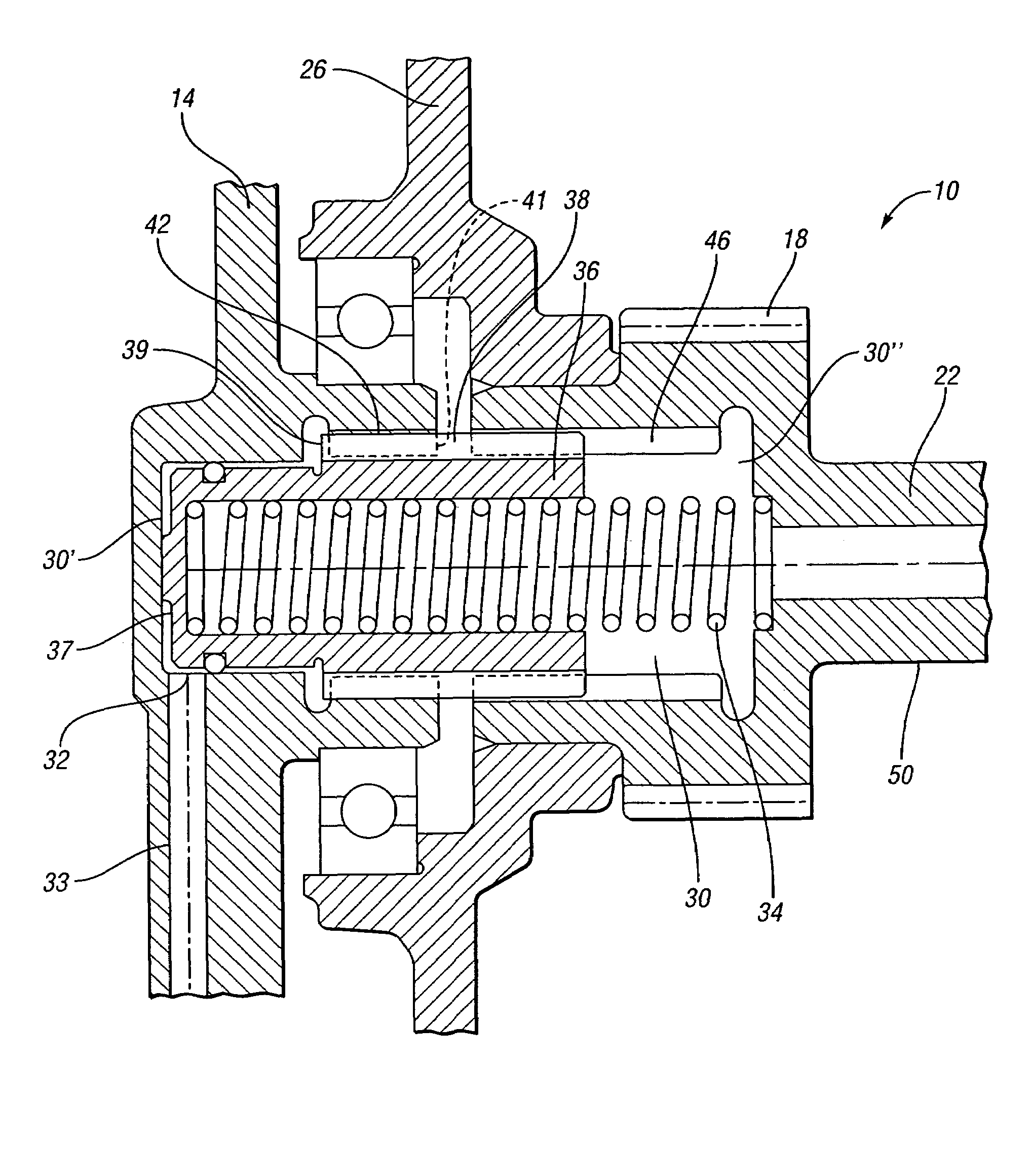
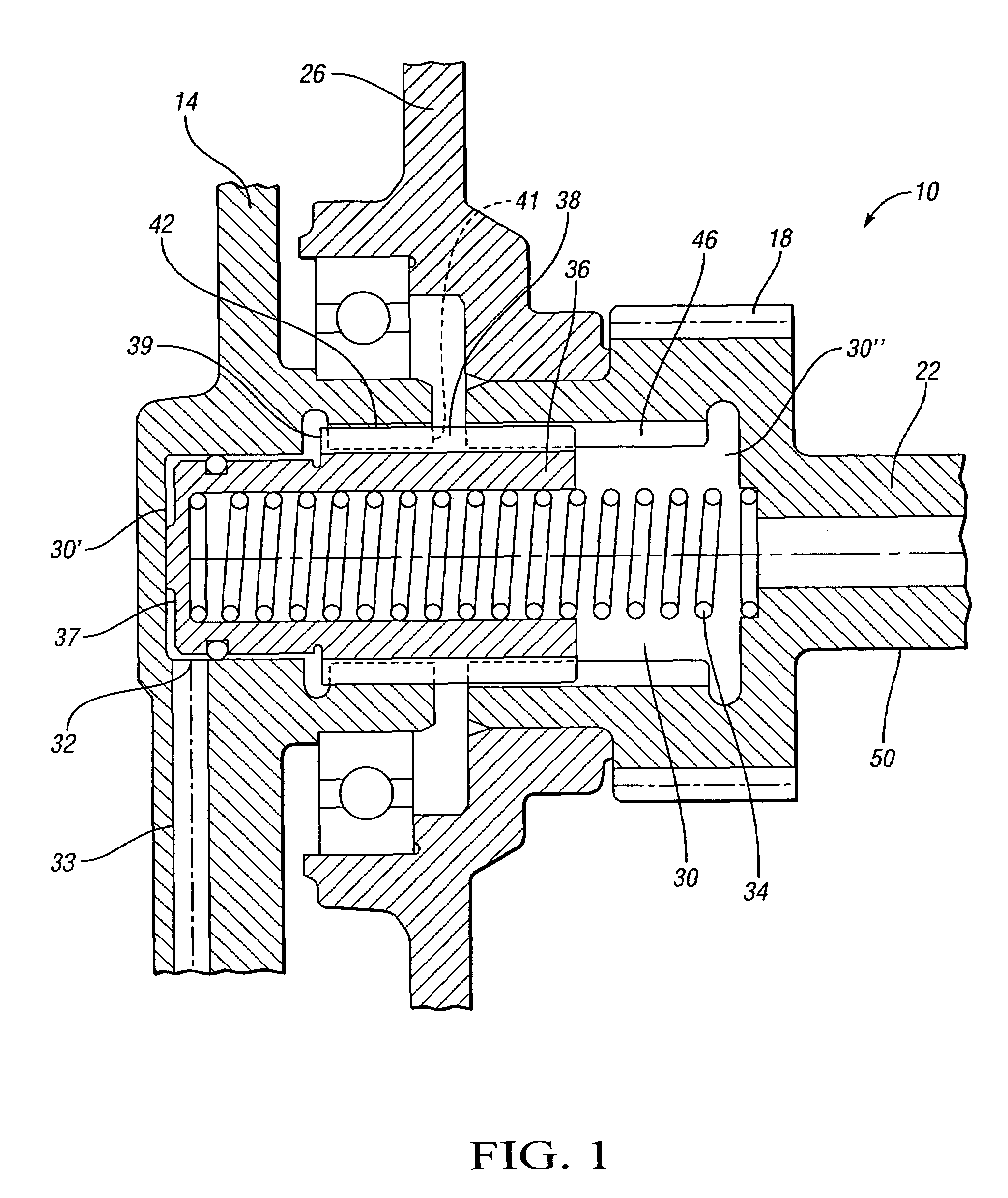
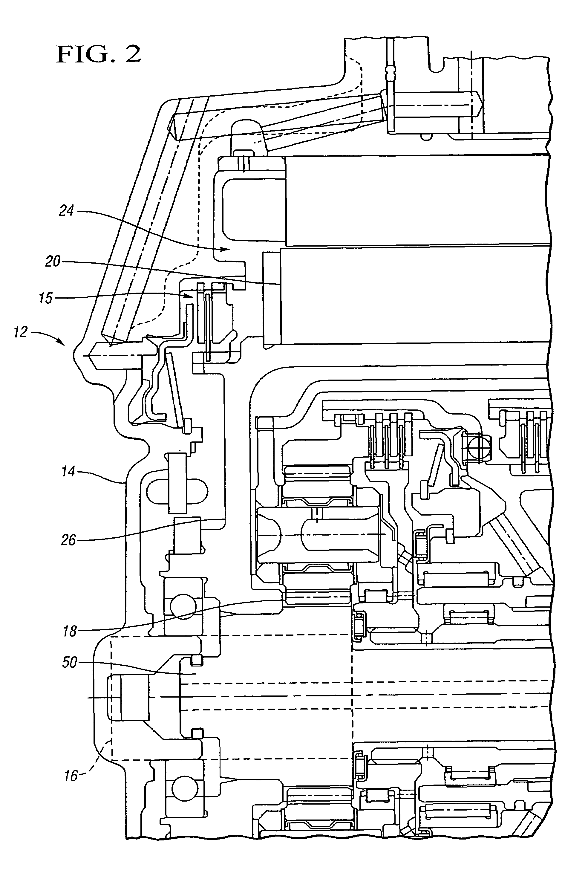
[0016]FIG. 1 shows a clutch 10 in accordance with the present invention for use in combination with and modification of an electrically-variable transmission (EVT) 12, as partially illustrated in FIG. 2. The clutch 10, which may be a dog clutch, operates between a transmission housing 14 (which may be the actual transmission housing or a transmission cover) and a sun gear 18 on a sun gear shaft 22. The sun gear 18 is attached or affixed to a rotor hub 26 which supports a rotor 20 in an electrical power unit 24, as shown in FIG. 2. The brake clutch 15 illustrated in FIG. 2 is the clutch that has been improved and relocated to the area 16 by the present invention.

[0017]The clutch 10 components are partially located within a clutch cavity 30. The clutch cavity 30 is defined by the transmission housing 14 at one end and the sun gear 18 or sun gear shaft 22 at the other end. The clutch cavity 30 may be defined by a first clutch cavity portion 30′ and a second clutch cavity portion 30″, t...


PUM


Abstract

A hydraulically-actuatable clutch and method is operable as an overdrive clutch in a transmission system having a transmission main shaft portion. The clutch is engageable between a transmission housing and a sun gear and rotor hub to provide for grounding of the sun gear and rotor hub to the transmission housing. The clutch may either be engaged or disengaged from the transmission housing. The clutch does not allow the rotor and sun gear to rotatably slip with respect to the transmission housing when the clutch is engaged to ground the rotor and sun gear to the transmission housing. When the clutch is disengaged, the rotor and sun gear may rotate with the transmission main shaft portion.

Description

CROSS REFERENCE TO RELATED APPLICATIONS[0001]This application claims the benefit of U.S. Provisional Application No. 60 / 602,849 filed Aug. 19, 2004, which is hereby incorporated by reference in its entirety.TECHNICAL FIELD[0002]A clutch operable as an overdrive clutch in a transmission system is provided.BACKGROUND OF THE INVENTION[0003]The transmission of power in an electromechanical transmission is described in commonly assigned U.S. Provisional Application Ser. No. 60 / 590,427, Holmes et al., entitled “Electrically Variable Transmission with Selective Fixed Ratio Operation,” filed Jul. 22, 2004, and hereby incorporated by reference in its entirety.[0004]A dog clutch is a mechanical clutch that provides a solid lock when engaged and does not allow for any slipping. Thus, a dog clutch only has two positions: engaged and disengaged. Dog clutches are known to be used in vehicle transmission systems. For example, a dog clutch in a continuously variable transmission is described in com...

Claims


Application Information

Patent Timeline
Patent Type & Authority Patents(United States)
IPC IPC(8): F16H3/44F16D11/14F16D25/061F16D63/00
CPCF16D25/061F16H63/3023Y10T74/19637F16H3/54
Inventor SOWUL, HENRYKPOHL, MICHAEL H.
Owner GM GLOBAL TECH OPERATIONS LLC
Why Eureka
Try Eureka