Method and device for determining the mechanical axis of a femur

a mechanical axis and femur technology, applied in the field of determining the mechanical axis of the femur, can solve the problems of patient pain and increase the pain of patients, and achieve the effect of great accuracy

Active Publication Date: 2008-02-19
AESCULAP AG
View PDF7 Cites 116 Cited by
  • Summary
  • Abstract
  • Description
  • Claims
  • Application Information

AI Technical Summary

Benefits of technology

[0016]It is, in addition, advantageous when the position data of the partial spherical surface are converted to a uniform pivoting angle relative to the initial position using the position data of the virtual center point so that corrected position data defining a common circle are obtained therefrom and when the mid-vertical of this circle is calculated as mechanical axis of the femur. All the position data obtained...

Problems solved by technology

This method operates reliably but has the disadvantage that an additional marking element must be arranged...

Method used


Image

  • Method and device for determining the mechanical axis of a femur
  • Method and device for determining the mechanical axis of a femur
  • Method and device for determining the mechanical axis of a femur

Examples


Embodiment Construction

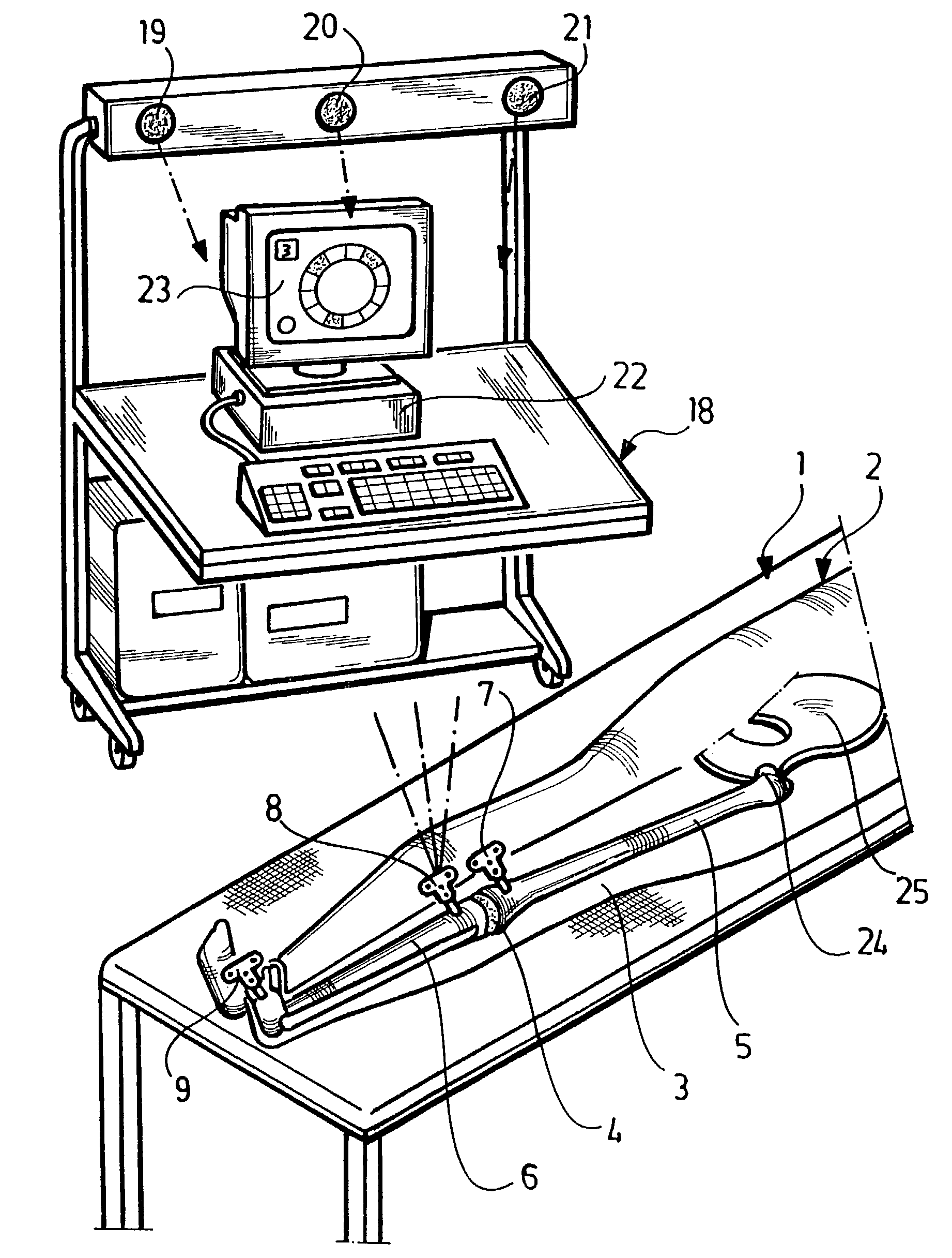
[0030]A patient 2 lying on an operating table 1, for whom the knee joint 4 in one leg 3 is intended to be replaced by an endoprosthesis, is illustrated schematically in FIG. 1.

[0031]In order to prepare for this operation it is necessary to determine the orientation of the prosthesis parts to be used relative to the bones, i.e., relative to the femur or thigh bone 5 and, where applicable, also relative to the shin bone 6.

[0032]For this purpose, a marking element 7 is inserted into the femur 5 in the vicinity of the knee joint 4, for example, by screwing it in and, in addition, corresponding marking elements 8, 9 into the shin bone 6 which are not, however, of significance for the method of interest in this case.

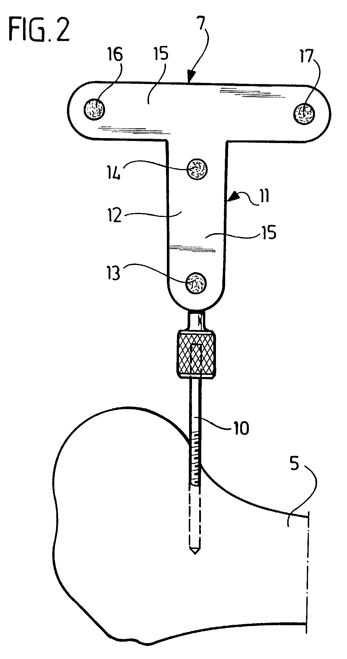
[0033]In FIG. 2, a marking element 7 of this type is illustrated; it comprises a foot 10 in the form of a bone screw which can be screwed into the femur and a T-shaped attachment member 11 which has two radiation transmitters 13, 14 at a distance from one another on its arm 12...


PUM


Abstract

In order to avoid the use of a marking element on the pelvic bone in a method for determining the mechanical axis of a femur, with which the femur is moved about the hip joint, the movement of the femur is followed via a navigation system by means of a marking element on the femur, position data of the femur obtained therefrom are stored and the position of the mechanical axis of the femur is calculated relative to the same from the various position data of the femur in various positions, it is suggested that the femur be pivoted from an initial position only through a maximum pivoting angle of 15° in various directions and that the mechanical axis of the femur be calculated from the position data of the surface area thereby covered by the marking element and from the position data of the knee joint otherwise determined. In addition, a device for carrying out this method is described.

Description

[0001]The present disclosure relates to the subject matter disclosed in International application No. PCT / EP01 / 12141 of Oct. 20, 2001, which is incorporated herein by reference in its entirety and for all purposes.BACKGROUND OF THE INVENTION[0002]The invention relates to a method for determining the mechanical axis of a femur, with which the femur is moved about the hip joint, the movement of the femur is followed via a navigation system by means of a marking element on the femur, position data of the femur obtained therefrom are stored and the position of the mechanical axis of the femur is calculated relative to the same from the various position data of the femur in various positions.[0003]WO 98 / 40037 describes such a method, wherein marking elements are attached to the hip and to the femur for determining the mechanical axis of the femur, the movement of these marking elements during pivoting of the femur about the hip joint being recorded; the position of the hip joint is deter...

Claims


Application Information

Patent Timeline
IPC IPC(8): A61B5/103A61B5/117A61B5/11A61B17/15A61B19/00A61B34/10A61B34/20A61B90/00G01S5/16G01S5/18G01S15/87G01S17/87
CPCA61B5/1114A61B5/1121A61B5/1127A61B5/4528A61B17/154A61B19/52A61B19/5244G01S5/163G01S5/186G01S15/872G01S17/87A61B5/4504A61B19/56A61B2017/00128A61B2019/505A61B2019/5255A61B2019/5272A61B2019/5276A61B90/36A61B2034/2055A61B2034/2072A61B34/20A61B34/25A61B2034/105A61B2090/378
Inventor LEITNER, FRANCOIS
Owner AESCULAP AG
Why Eureka
Try Eureka