Adaptive tourniquet cuff system

a tourniquet and cuff technology, applied in the field of adaptive tourniquet cuff systems, can solve the problems of compromising sterility, unsafe conditions, and inability to function predictably or properly, and achieve the effects of reducing safety and operational features, reducing safety, and reducing safety

Inactive Publication Date: 2008-02-19
WESTERN CLINICAL ENG
View PDF38 Cites 33 Cited by
  • Summary
  • Abstract
  • Description
  • Claims
  • Application Information

AI Technical Summary

Problems solved by technology

Such safety features and operational features in a tourniquet instrument may not function, or may not function predictably or properly if a cuff from an unknown manufacturer is connected to the tourniquet instrument.
Subsequent sterilization or processing may lead to hazardous conditions such as compromised sterility, deteriorated physical condition and possibly sudden failure of the cuff during surgery.
In particular, exposure to high temperatures or ethylene oxide gas during sterilization can degrade the materials in these cuffs.
No communication with a tourniquet instrument is automatically established by connection of the cuff to the instrument, and therefore the instrument necessarily cannot automatically adapt the settings of important parameters of operation and safety in response to the size and type of cuff connected to the instrument.
This can present a hazard to the patient under some circumstances.
Also, inclusion of electrical components within the tourniquet cuff significantly increases the cost and complexity of manufacture of such cuffs, and their reliability at time of manufacture and subsequently during use.
Further, fundamental problems inherent in the significantly increased cost and complexity, and in the inherently decreased reliability, of the apparatus described in McEwen '010, have prevented the commercial realization of any tourniquet systems incorporating apparatus such as described in McEwen '010.

Method used


Image

  • Adaptive tourniquet cuff system
  • Adaptive tourniquet cuff system
  • Adaptive tourniquet cuff system

Examples


Embodiment Construction

[0022]A specific embodiment illustrated is not intended to be exhaustive or to limit the invention to the precise form disclosed. It is chosen and described in order to explain the principles of the invention and its application and practical use, and thereby enable others skilled in the art to utilize the invention.

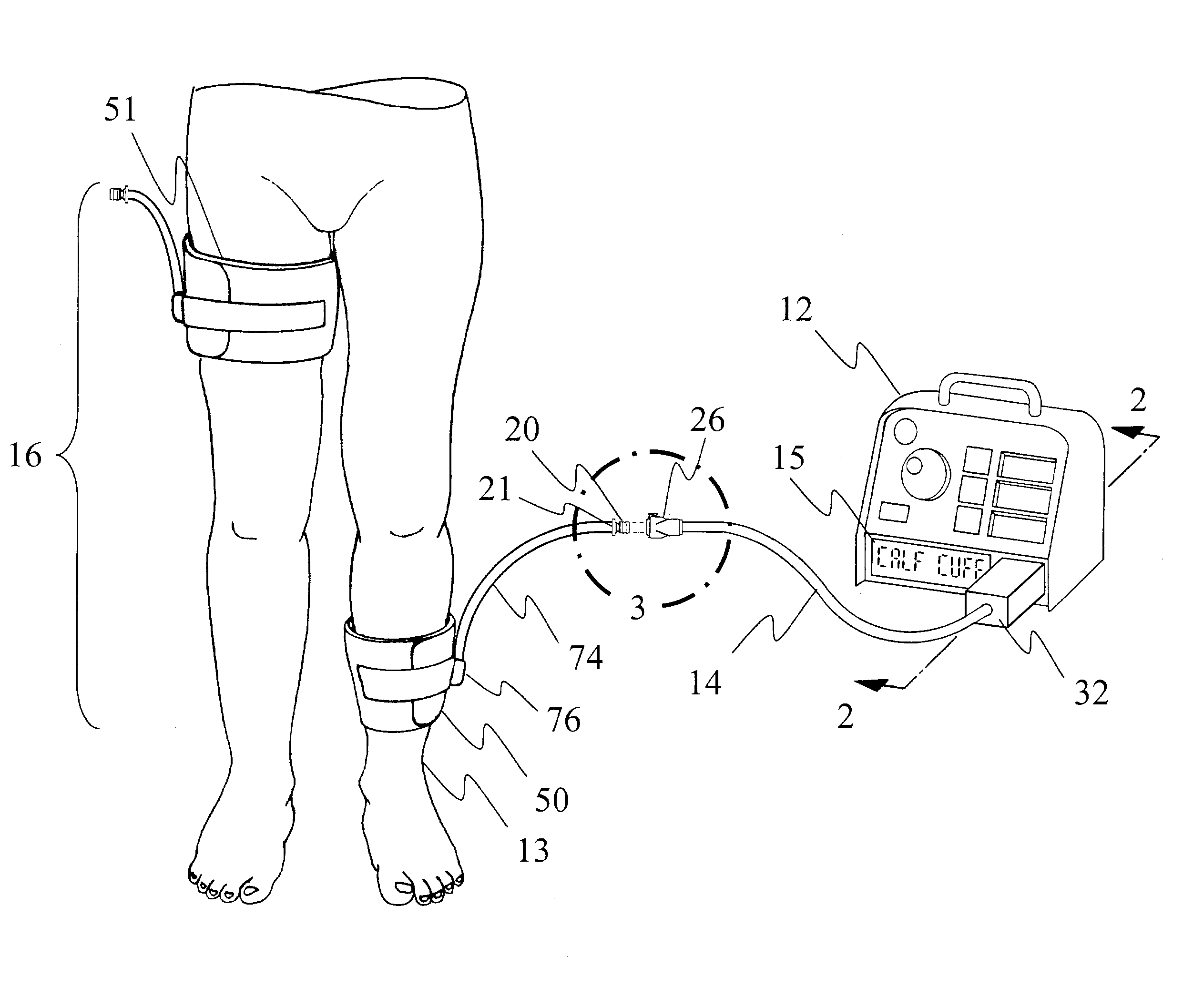
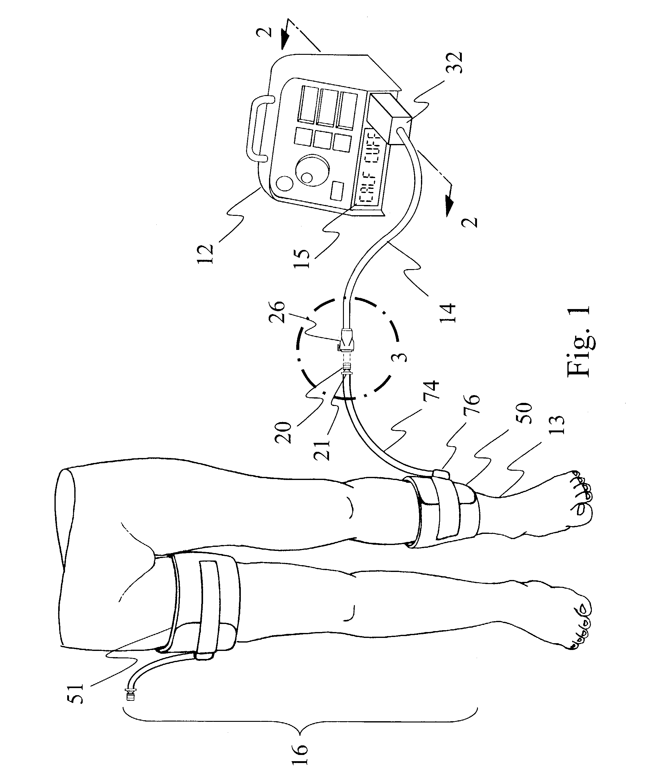
[0023]FIG. 1 shows the preferred embodiment of the invention consisting of tourniquet instrument 12, fill line assembly 14, and cuff set 16. Fill line assembly 14 includes fill line connector 26 and cuff identification module 32. Cuff set 16 comprises contour calf cuff 50 which has physical characteristics suitable for application to a lower leg within size and shape limits and contour thigh cuff 51 which has different physical characteristics suitable for application to a thigh within different size and shape limits. For clarity, physical characteristics of cuff 50 and cuff 51 include their size, shape, materials, and stiffness. Also for clarity, a physical characterist...


PUM


Abstract

An adaptive tourniquet cuff system comprises: a tourniquet cuff having a physical characteristic and including an inflatable bladder of a length greater than the circumference of a limb at a selected location; a cuff connector carried on the cuff and communicating pneumatically with the bladder for releasably connecting to a tourniquet instrument to establish a gas-tight passageway between the bladder and the tourniquet instrument; and an identifying collar including identification means indicative of the physical characteristic and detectable by the tourniquet instrument upon establishment of the gas-tight passageway. The tourniquet instrument may supply gas to the bladder through the gas-tight passageway at a pressure sufficient to stop arterial blood flow into the limb distal to the cuff at the selected location, and may adapt its operation in response to the detected physical characteristic of the cuff.

Description

CROSS REFERENCE TO RELATED APPLICATION[0001]This application is a continuation-in-part of U.S. patent application No. 09 / 920,341, filed Aug. 14, 2001, now U.S. Pat. No. 6,682,547.BACKGROUND[0002]The use of an inflatable tourniquet cuff to occlude blood flow into a subject's limb, thereby providing a bloodless surgical field in the portion of the limb distal to the cuff over a period of time suitably long for the performance of a surgical procedure, is well known in surgical practice. Tourniquet systems typically include an inflatable cuff for encircling a limb at a selected location and a tourniquet instrument for maintaining the pressure in the cuff near a selected pressure. Such tourniquet instruments of the prior art typically contain, or connect to, a source of pressurized gas and include a pressure regulating mechanism for controlling and maintaining the pressure of the gas supplied to the tourniquet cuff near the selected pressure.[0003]Typically a variety of cuff sizes are pr...

Claims


Application Information

Patent Timeline
Patent Type & Authority Patents(United States)
IPC IPC(8): A61B17/00A61B17/135A61B19/00
CPCA61B17/135A61B17/1355A61B2017/00482A61B2019/444A61B2562/08A61B90/92
Inventor MCEWEN, JAMES A.INKPEN, KEVIN B.JAMESON, MICHAEL
Owner WESTERN CLINICAL ENG
Why Eureka
Try Eureka