

Anchoring device for an endoluminal prosthesis
- Summary
- Abstract
- Description
- Claims
- Application Information
AI Technical Summary
Benefits of technology
Problems solved by technology
Method used
Image

Examples
Embodiment Construction
[0015]The following detailed description illustrates the invention by way of example, not by way of limitation, the principles of the invention. This description will clearly enable one skilled in the art to make and use the invention, and describes several embodiments, adaptations, variations, alternatives and uses of the invention, including what we presently believe is the best mode of carrying out the invention.
[0016]The invention will be described by way of illustration with reference to a particular application of the present invention, namely for use with a AAA prosthesis. One of skill in the art should appreciate, however, that the present invention could equally be utilized in countless other endoluminal prostheses, such as bare stents.
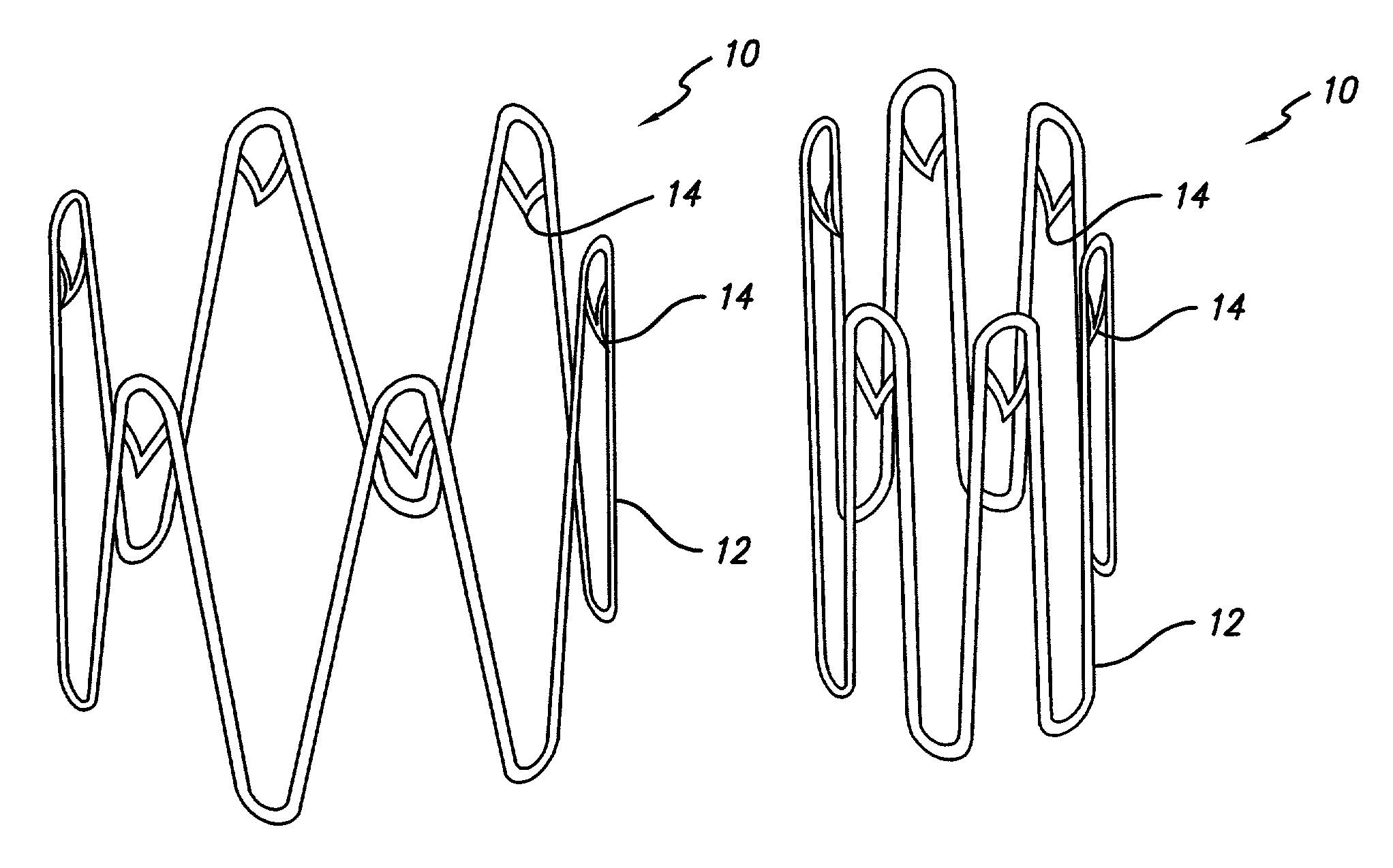
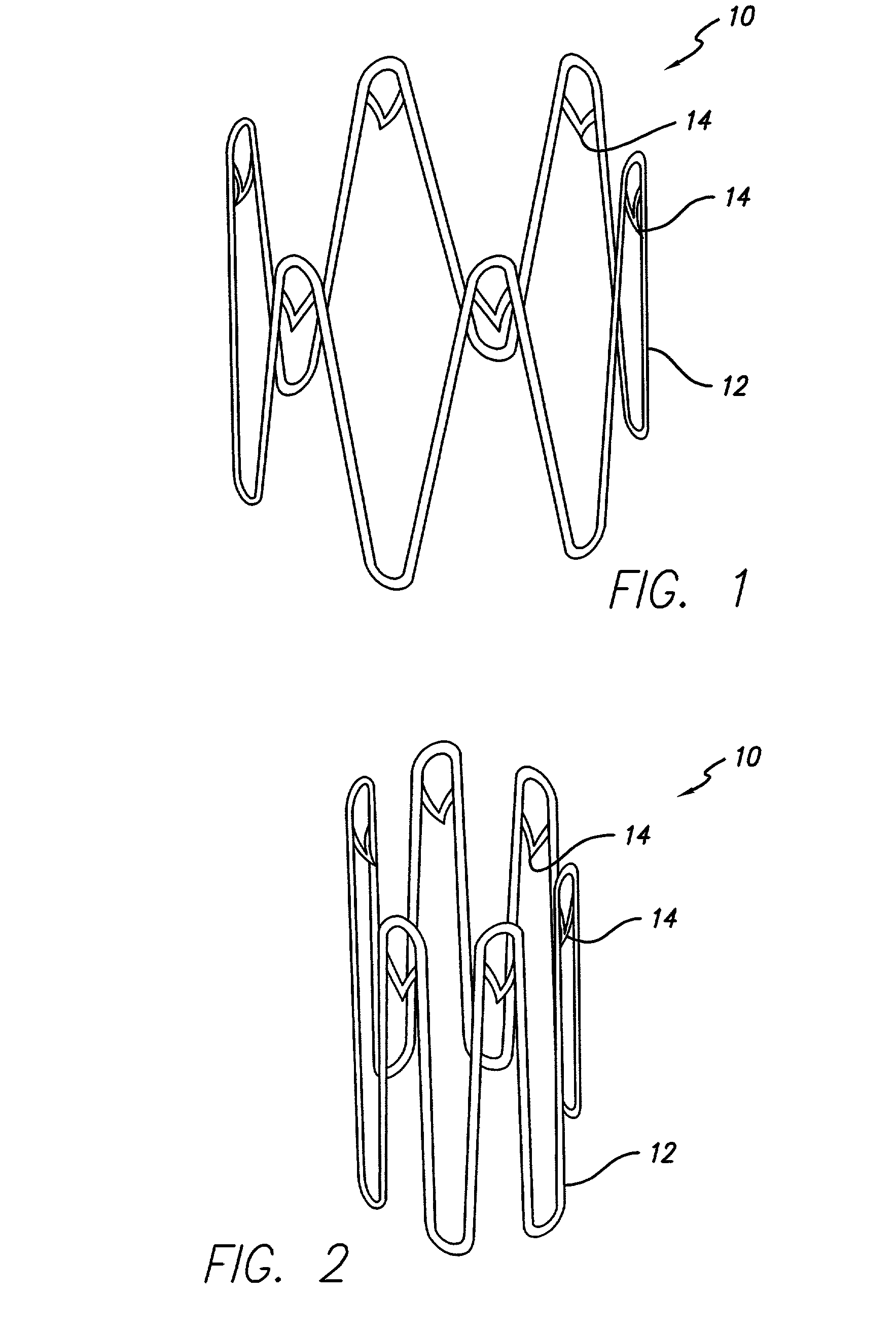
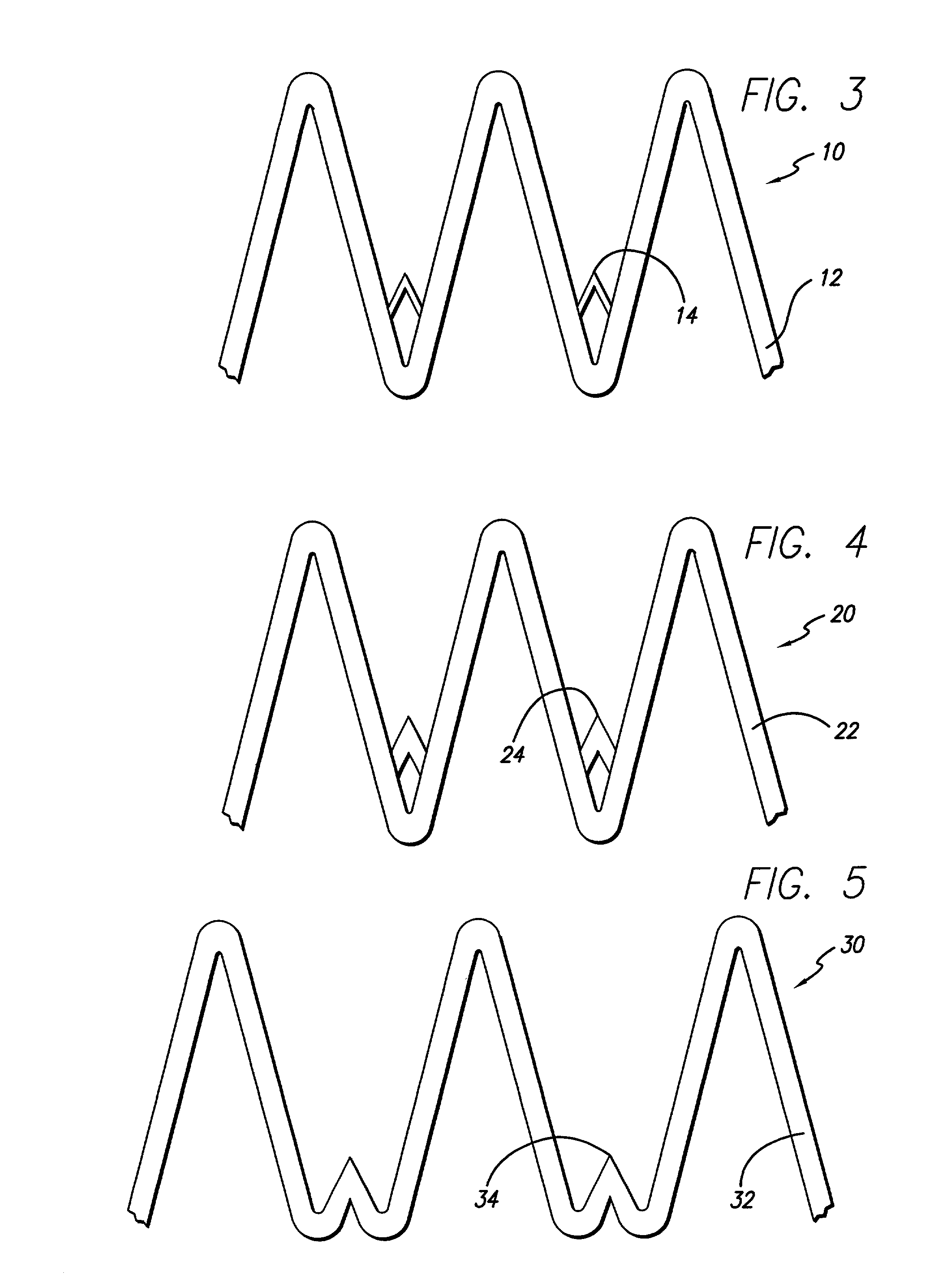
[0017]Referring now to FIG. 1, a preferred embodiment of the anchoring system of the present invention is illustrated. A ring stent 10 is shown having a body portion 12 and anchors 14. As shown in FIG. 1, the ring stent 10 is illustrated in i...
PUM
 Abstract
Description
Claims
Application Information