Photomultiplier tube with dynode modulation for photon-counting

a technology of photomultiplier tube and dynode, applied in the field of photomultiplier tube, can solve the problems of two techniques not being combined, the frequency of phase relationship of the electron is difficult to accurately resolve, and the electron is multiplied improperly

Active Publication Date: 2008-02-19
OCUMETRICS
View PDF24 Cites 4 Cited by
  • Summary
  • Abstract
  • Description
  • Claims
  • Application Information

AI Technical Summary

Problems solved by technology

However, some of these electrons do not strike the first dynode or deviate from their normal trajectories, thereby causing electrons to have different transit times through the PMT, which in turn may cause the electrons to be multiplied improperly.
Since the modulation frequencies required to detect common fluorophores often vary between tens and / or hundreds of megahertz, it is difficult to accurately resolve phase relationships at these frequencies.
Additionally, the PMT typically introduces a statistically random phase delay known as transit-time spread that is compounded by each stage of photon multiplication associated with each dynode electrode in the tube, which is undesirable.
Unfortunately, the modulated voltage at dynode DY2 is coupled through the inter-electrode capacitance inherent in the PMT to the anode P, where it is undesirably superimposed on the output.
While it is generally recognized that photon-counting is best for low photon flux applications (low light levels) and that modulated PMT cross-correlation phase-modulated systems are a relatively inexpensive and reliable way to measure the lifetimes of common fluorophores, these two techniques haven't been combined due to the fundamental limitations of the inter-electrode capacitance within the PMT itself.
The modulation signal feed through can easily swamp the pulse-discriminator circuitry used in photon-counting, making it difficult to obtain any meaningful information.
Since the output pulses from the PMT have energy primarily in the 100-300 MHz band, a simple high-pass filter on the anode output which significantly attenuates the spurious modulation signal will not preserve the amplitude of the photon pulses; the phase dispersion will suppress the peaks of these pulses below the noise floor.

Method used


Image

  • Photomultiplier tube with dynode modulation for photon-counting
  • Photomultiplier tube with dynode modulation for photon-counting
  • Photomultiplier tube with dynode modulation for photon-counting

Examples


Embodiment Construction

[0019]Embodiments of the present invention are described below with respect to an exemplary PMT device for simplicity only. It is to be understood that embodiments of the present invention are equally applicable to other PMT devices and architectures, both known and yet-to-be developed. In the following description, for purposes of explanation, specific nomenclature is set forth to provide a thorough understanding of the present invention. In other instances, well-known circuits and devices are shown in block diagram form to avoid obscuring the present invention. Further, the logic levels assigned to various signals in the description below are arbitrary and, thus may be modified (e.g., reversed polarity) as desired. Accordingly, the present invention is not to be construed as limited to specific examples described herein but rather includes within its scope all embodiments defined by the appended claims.

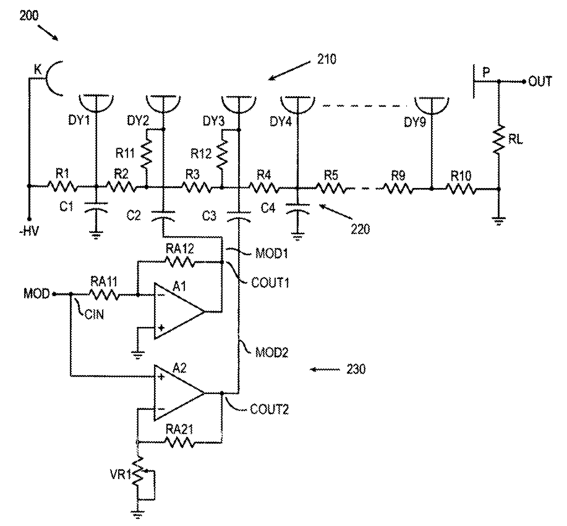
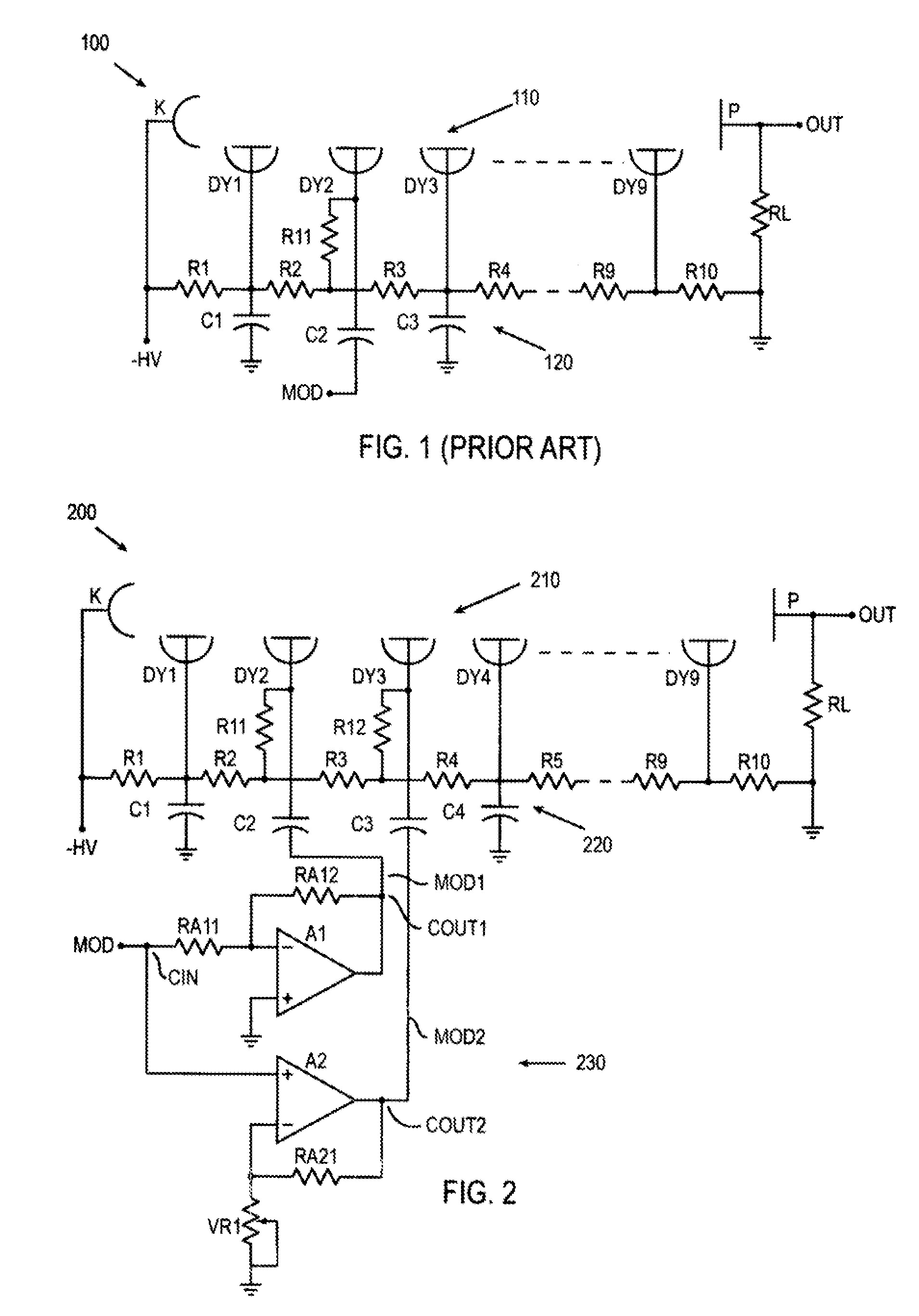
[0020]FIG. 2 shows a PMT 200 in accordance with some embodiments of the present...


PUM


Abstract

In a photomultiplier tube (PMT) device having a plurality of dynodes provided between a cathode and an anode, a cancellation circuit provides two different modulation signals to the PMT to cancel the effects of the modulation signals upon the output of the PMT. For one embodiment, a cancellation circuit includes an input to receive an input modulation signal, a first output to provide a first output modulation signal to a first dynode, and a second output to provide a second output modulation signal to a second dynode, wherein the first and second output modulation signals are 180 degrees out-of-phase. For another embodiment, the cancellation circuit provides the input modulation signal to one of the PMT's dynodes, and also subtracts the input modulation signal from the PMT's output signal.

Description

CROSS-REFERENCE TO RELATED APPLICATION[0001]This application claims the benefit under 35 USC §119(e) of the co-pending and commonly owned U.S. Provisional Patent Application No. 60 / 565,343 entitled “Cross-Correlation Phase-Modulated Fluorescence Spectroscopy using Photon Counting” filed on Apr. 26, 2004, and incorporated herein by reference.GOVERNMENT FUNDING[0002]Some aspects of the present invention were funded by the NIH via grant number R43BY014517.FIELD OF INVENTION[0003]This invention relates generally to photomultiplier tubes (PMT) for photon counting.DESCRIPTION OF RELATED ART[0004]Recently, non-destructive and non-invasive measurement using light is becoming more and more popular in diverse fields including biological, chemical, and medical fields, for example, use low-light-level measurement by detecting fluorescence emitted from cells labeled with a fluorescent dye. In many clinical testing and medical diagnosis, techniques involving low-light-level measurement such as fl...

Claims


Application Information

Patent Timeline
Patent Type & Authority Patents(United States)
IPC IPC(8): H01J43/04H01J21/20H01J40/14H01J43/30
CPCH01J43/30
Inventor ISHIMOTO, BRUCE MASATOHAWKS, TIM
Owner OCUMETRICS
Why Eureka
Try Eureka