Landmark, apparatus, and method for effectively determining position of autonomous vehicles

a technology for autonomous vehicles and landmarks, applied in the field of image recognition and tracking, can solve the problems of low accuracy of dead reckoning methods, low accuracy of inertial navigation, and drawbacks of methods

Active Publication Date: 2008-02-19
SAMSUNG ELECTRONICS CO LTD
View PDF6 Cites 38 Cited by
  • Summary
  • Abstract
  • Description
  • Claims
  • Application Information

AI Technical Summary

Benefits of technology

[0012]The present invention provides a landmark used to effectively determine the location of an autonomous vehicl

Problems solved by technology

However, these methods have drawbacks.
For example, the dead reckoning method has a low accuracy due to an accumulation of errors caused by slipping of autonomous vehicles.
The inertial navigation has a low accuracy due to an accumulation of errors caused by integration.
The satellite-based positioning method requires a secure communications path with a satellite and cannot provide accurate location information necessary for orbit correction.
However, current methods using landmarks have s

Method used


Image

  • Landmark, apparatus, and method for effectively determining position of autonomous vehicles
  • Landmark, apparatus, and method for effectively determining position of autonomous vehicles
  • Landmark, apparatus, and method for effectively determining position of autonomous vehicles

Examples


Embodiment Construction

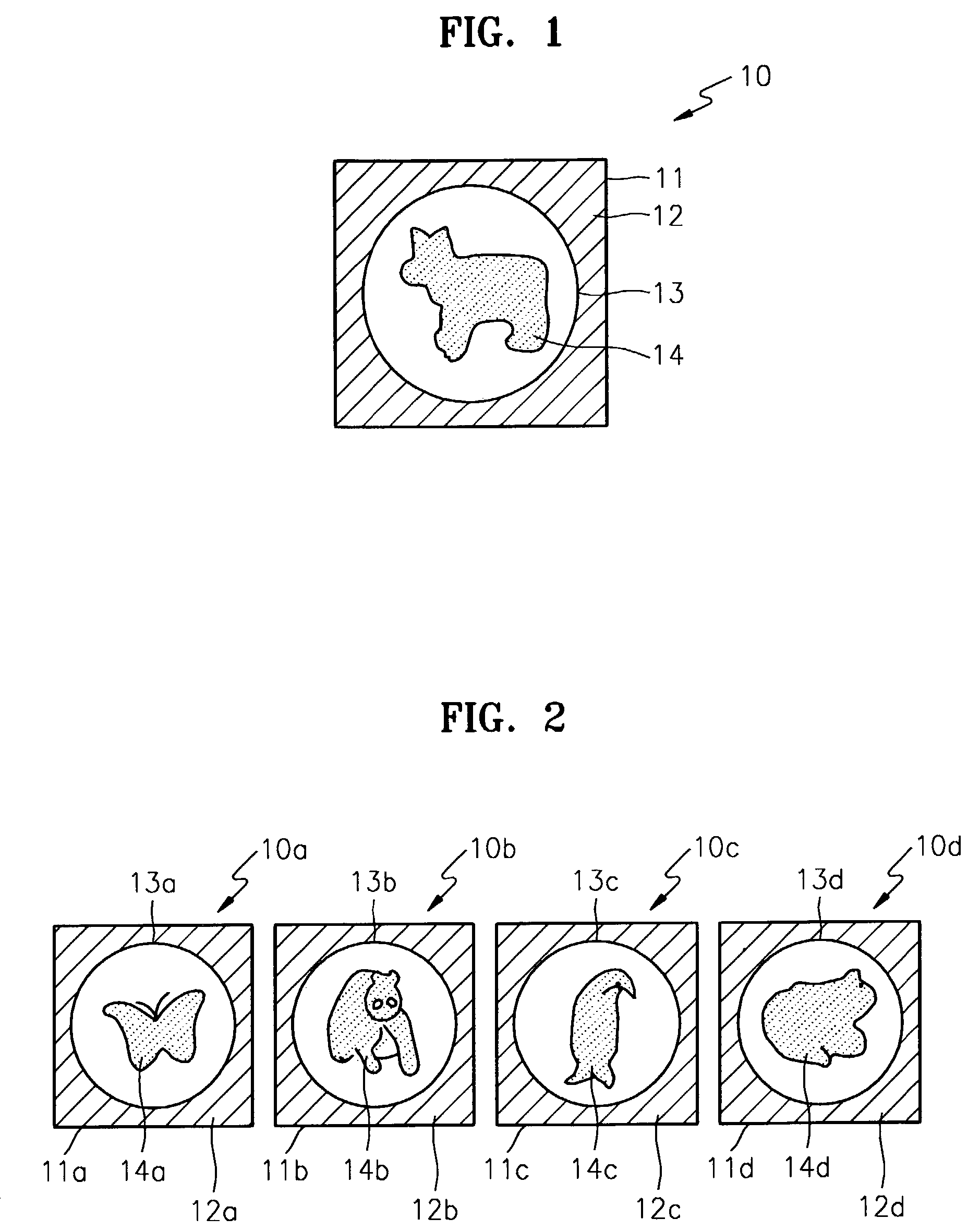
[0030]FIG. 1 shows a configuration of a landmark 10 according to a preferred embodiment of the present invention. FIG. 2 shows various landmarks 10a through 10d according to the present invention.

[0031]Referring to FIG. 1, the landmark 10 includes a first outer line area 11, a color area 12, a second outer line area 13, and a shape area 14. The first outer line area 11 corresponds to the outer line of the landmark 10 in a rectangular shape and is used as an index for indicating the X and Y axes of an image plane upon self-localization of an autonomous vehicle. The second outer line area 13 is formed in a perfect circular shape with a predetermined radius. To ascertain a degree of deviation between a camera and an object, a deformation of the circle 13 generated upon projection of the camera upon the landmark 10 is analyzed, that is, a phenomenon where a perfect circle appears to be an oval is analyzed. The color area 12, which exists between the first and second outer line areas, is...


PUM


Abstract

A landmark used to effectively determine the location of an autonomous vehicle, and a self-localization apparatus and method using the landmark are provided. In the self-localization method, first, first and second outer line information and shape information are extracted from a landmark image received from a camera. Next, a projective invariant is calculated from the shape information and stored in a hash table. Thereafter, the calculated projective invariant is compared with reference projective invariants for a plurality of landmarks stored in a predetermined data storage area in the form of a hash table, thereby determining which landmark corresponds to the landmark image. Then, information on the distance and orientation of the determined landmark with respect to the autonomous vehicle is analyzed in response to the first and second outer line information.

Description

[0001]This application claims the priority of Korean Patent Application No. 2002-59778, filed on Oct. 1, 2002, in the Korean Intellectual Property Office, the disclosure of which is incorporated herein in its entirety by reference.BACKGROUND OF THE INVENTION[0002]1. Field of the Invention[0003]The present invention relates to image recognition and tracking performed in application fields using images, such as, automation systems, intelligent vehicle systems, and the like, and more particularly, to a landmark used to effectively determine the location of an autonomous vehicle such as a mobile robot, and a self-localization apparatus and method using the landmark.[0004]2. Description of the Related Art[0005]With an increase in the interest in mobile robots, various types of such robots have been actively developed. Mobile robots are applied to various fields, and must have four functions associated with their movements in order to navigate autonomous vehicles.[0006]The first function ...

Claims


Application Information

Patent Timeline
IPC IPC(8): G06K9/00E01F9/06G06T7/20G06V10/42G06V10/46
CPCG06K9/00664G06K9/48G06K9/52G06K2209/29G06V20/10G06V10/42G06V10/46G06V2201/11G06T7/20
Inventor ROH, KYOUNG-SIGSON, YOUNGPARK, KI-CHEOLKWAK, JOO-YOUNG
Owner SAMSUNG ELECTRONICS CO LTD
Why Eureka
Try Eureka