
Ventilated mattress and method

a mattress and foam technology, applied in the field of mattresses, can solve problems such as its life, and achieve the effects of prolonging the life of the mattress, increasing the comfort of the bed, and keeping the mattress fresh

Active Publication Date: 2008-02-26
SWARTZBURG RICK T
View PDF11 Cites 96 Cited by
  • Summary
  • Abstract
  • Description
  • Claims
  • Application Information

AI Technical Summary

Benefits of technology

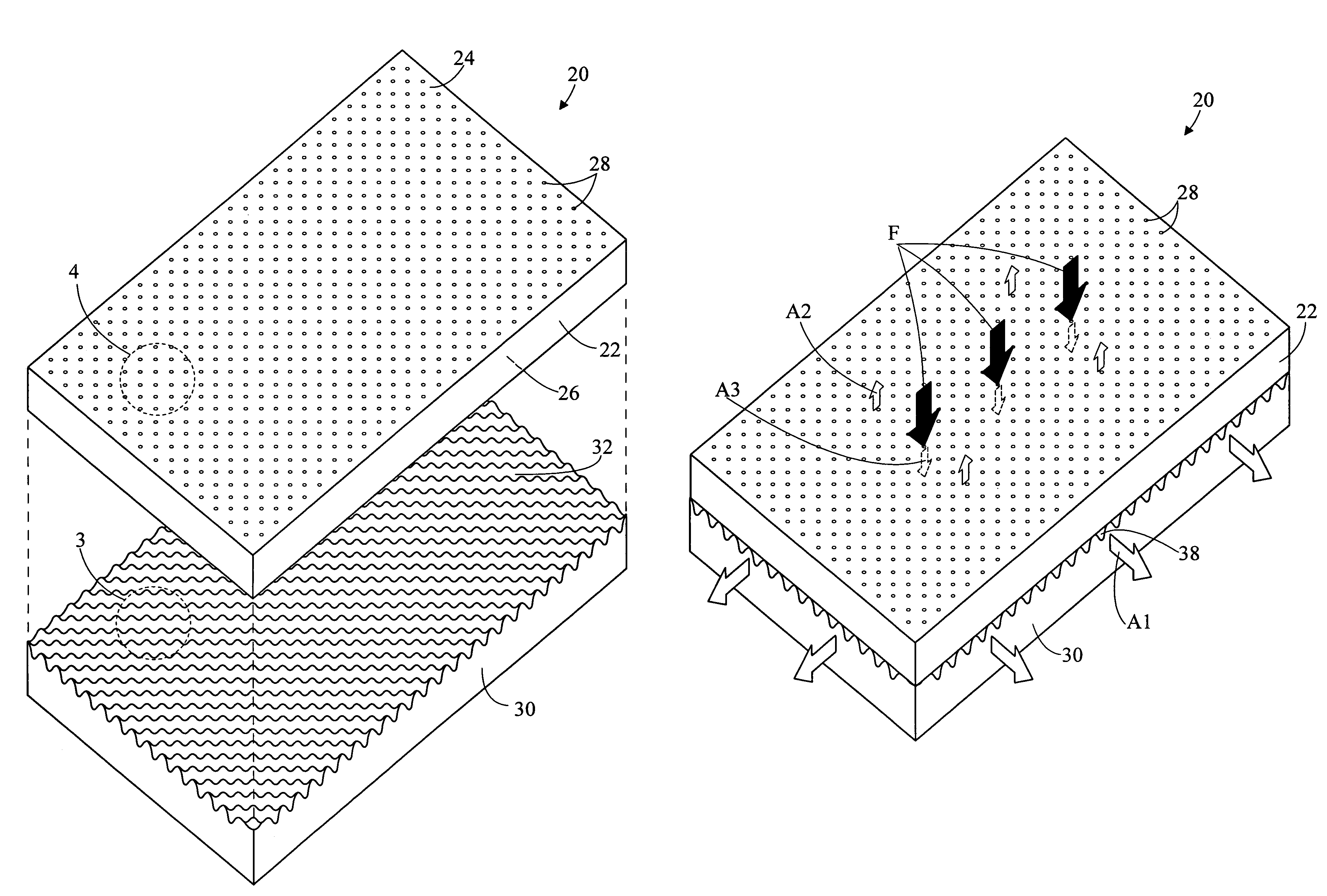
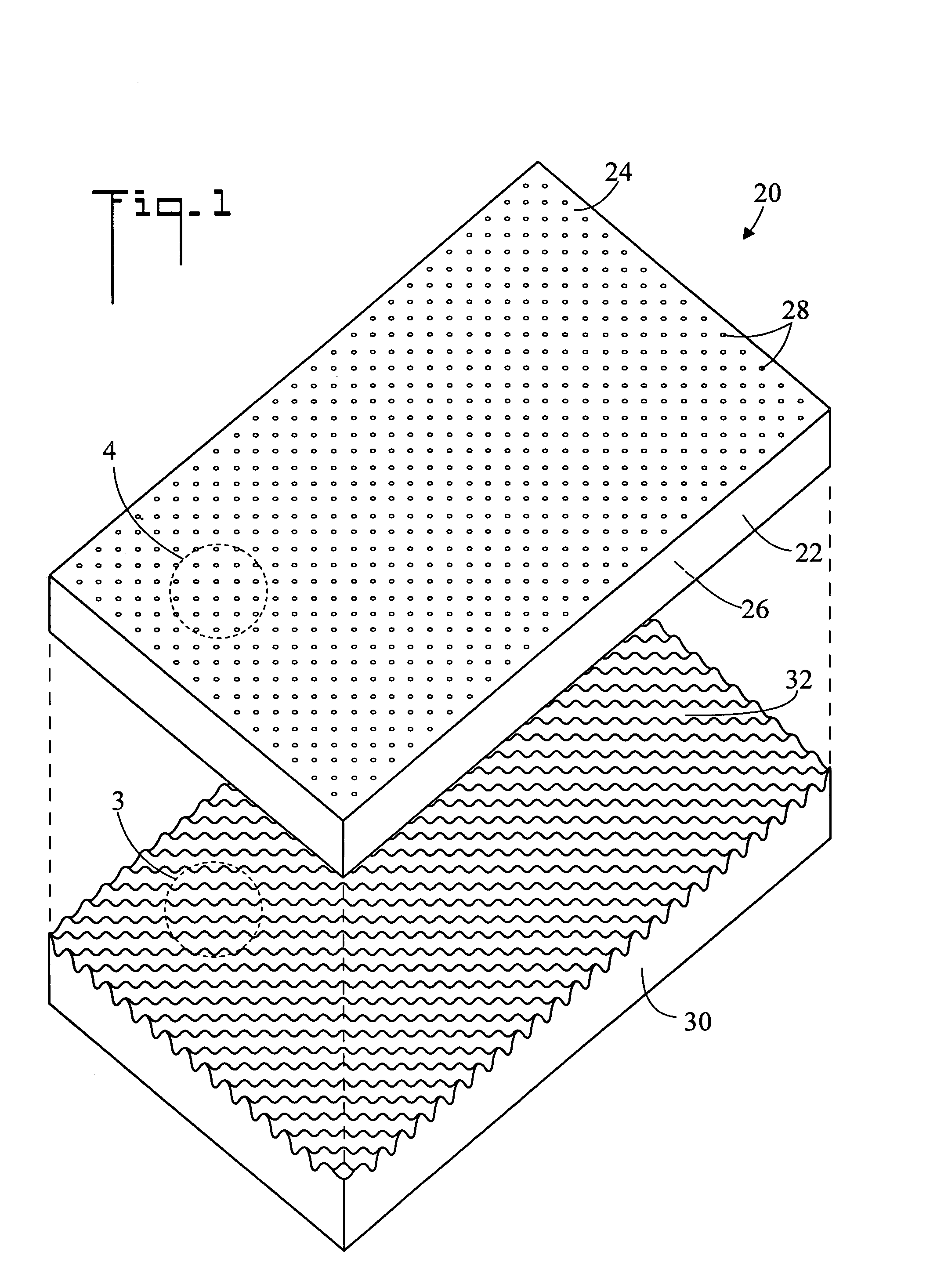
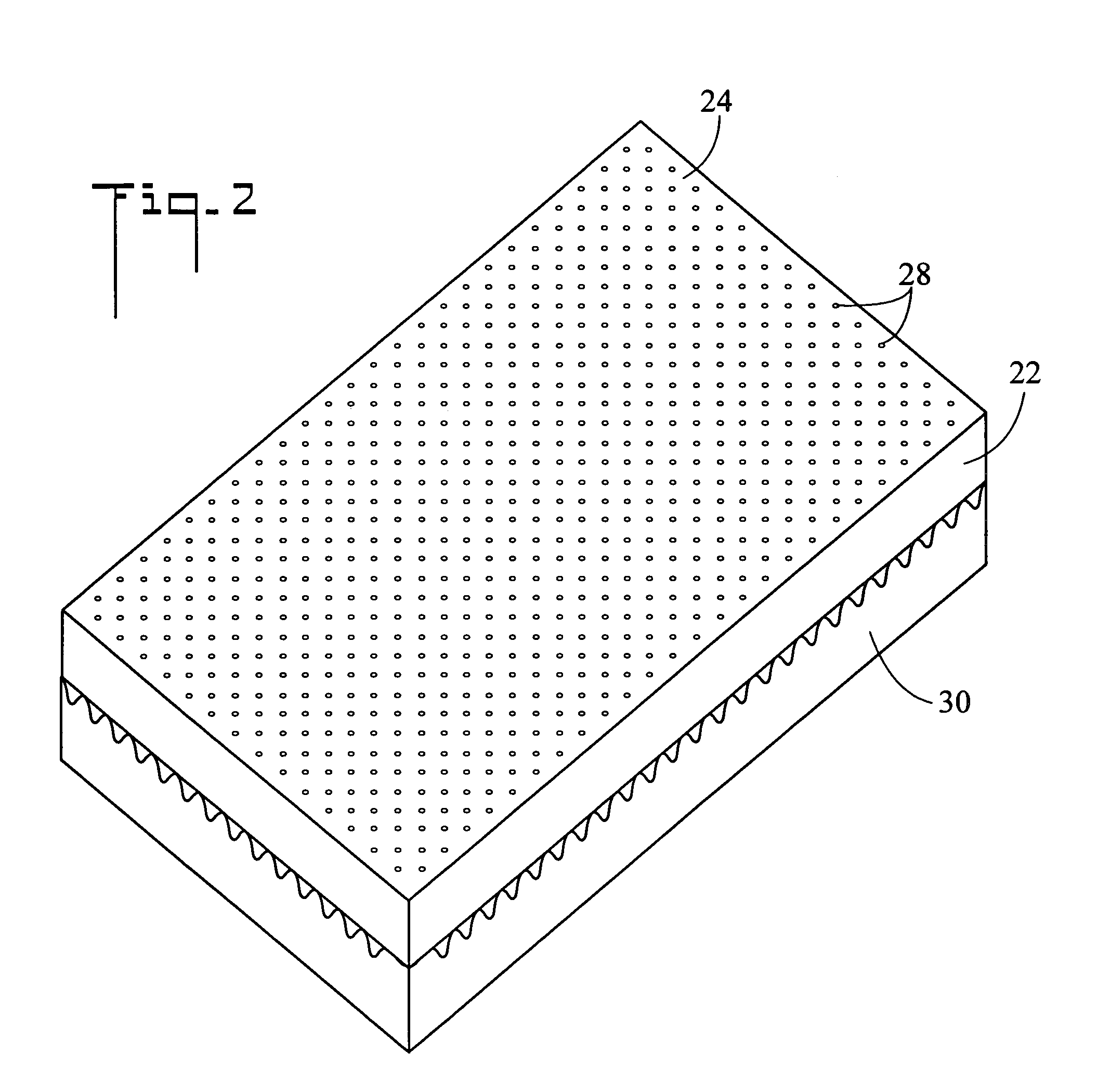
[0003]The present invention is directed to a ventilated foam mattress in which air flows both into and out of the mattress during normal mattress use. This air flow purges moisture, heat and unpleasant odors from the mattress, and thereby keeps the mattress fresh and prolongs its life. It also offers an increased measure of extra comfort when lying or rolling over on the mattress as the airflow exchange occurs. The mattress has at least two layers with the top layer being ventilated with vertical holes that open up to the layer below and allow air flow to circulate both up and down vertically through the holes. The bottom layer is convoluted having upward projections and valleys which create air flow channels or passageways which allow airflow to circulate horizontally both in and out of the side of the mattress.
[0005]The use of visco-elastic memory foam on the top foam layer results in a slower, but more consistent and longer lasting pumping of air through the holes and across the air channels. Also a higher ILD polyurethane bottom foam layer(s) will give better integrity and resiliency to the air channels created on the surface of the bottom layer, while still allowing a more comfortable transition from the layer(s) above.

Problems solved by technology

This air flow purges moisture, heat and unpleasant odors from the mattress, and thereby keeps the mattress fresh and prolongs its life.

Method used


Image

  • Ventilated mattress and method
  • Ventilated mattress and method
  • Ventilated mattress and method

Examples


Embodiment Construction

[0034]Referring initially to FIG. 1, there is illustrated an exploded perspective view of a ventilated mattress in accordance with the present invention, generally designated as 20. Ventilated mattress 20 includes a top foam layer 22 which has a first side 24 and an opposite second side 26. Top foam layer 22 also includes a plurality of spaced apart holes 28, the holes 28 extending all the way through top foam layer 22 from first side 24 to second side 26. In the shown embodiment, holes 28 are oriented vertically when ventilated mattress 20 is in its normal horizontal position. Ventilated mattress 20 also includes a bottom foam layer 30. Bottom foam layer 30 has an upward facing side 32 which has a convoluted surface which contains a plurality of upward projections 34 spaced apart by valley 36. That is, upward projections 34 and valleys 36 are disposed in an alternating pattern on upward facing side 32. In the shown embodiment, upward projections 34 include rounded peaks and valleys...


PUM


Abstract

A ventilated mattress includes a top foam layer having a plurality of spaced apart holes which extend through the thickness of the top foam layer. The top foam layer rests upon a bottom foam layer which has an upward facing side which has a convoluted surface containing upward projections which are spaced apart by valleys, thereby creating structural passageways for air to flow into and from the holes. When a force, such as the weight of a person, is applied to the top foam layer, air flows out the sides of the mattress through air passageways created by the upward projections and valleys of the convoluted surface. Conversely, when the force is removed air flow into the sides of the mattress through the air passageways.

Description

TECHNICAL FIELD[0001]The present invention pertains generally to mattresses, and more particularly to a ventilated foam mattress in which air flows both into and out of the mattress.BACKGROUND OF THE INVENTION[0002]Mattresses made from foam are well known in the art. These mattresses can be made of foams having different density (lb. values) and firmness (indentation load deflection, ILD values) to suit the needs of the particular user. However, a problem exists with a foam mattress because without ventilation, moisture, objectionable odors and heat can build up within the mattress. Some manufacture designs have attempted to solve this by placing convoluting on the surface of the foam directly underneath the user, but unfortunately, the comfort of the mattress suffers, as an uneven surface is not comfortable for many users. It is well known that visco-elastic memory foam does not breathe well, so some manufacture designs have proposed ventilation holes in the top layer of foam, but ...

Claims


Application Information

Patent Timeline
IPC IPC(8): A47C27/15
CPCA47C21/046A47C27/144A47C27/146A47C27/15
Inventor SWARTZBURG, RICK T.
Owner SWARTZBURG RICK T
Learn More