Equipment enclosure acoustical door with low impedance distributed air flow

Inactive Publication Date: 2008-02-26
GOOGLE LLC
View PDF31 Cites 24 Cited by
  • Summary
  • Abstract
  • Description
  • Claims
  • Application Information

AI Technical Summary

Benefits of technology

[0009]The door configuration and axis of pivoting allow the door to be pivoted 90 degrees to a fully open position exposing the entire interior surface area through which units are mounted into and removed from rack mounts even with an ide

Problems solved by technology

These attributes are usually not compatible with e

Method used


Image

  • Equipment enclosure acoustical door with low impedance distributed air flow
  • Equipment enclosure acoustical door with low impedance distributed air flow
  • Equipment enclosure acoustical door with low impedance distributed air flow

Examples


Embodiment Construction

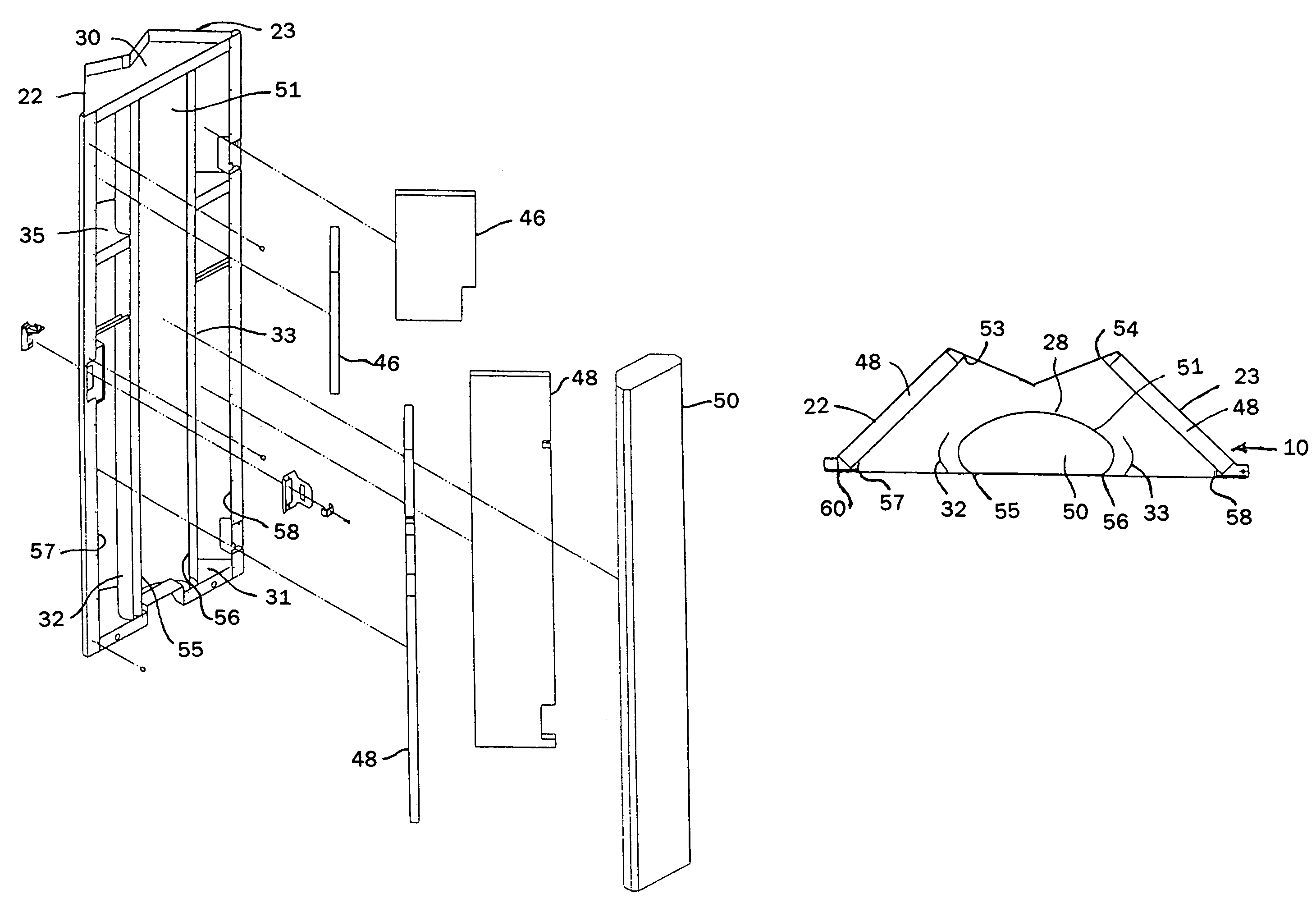
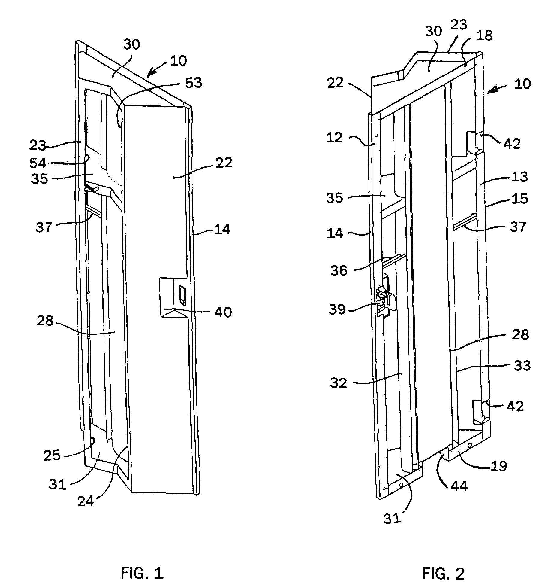
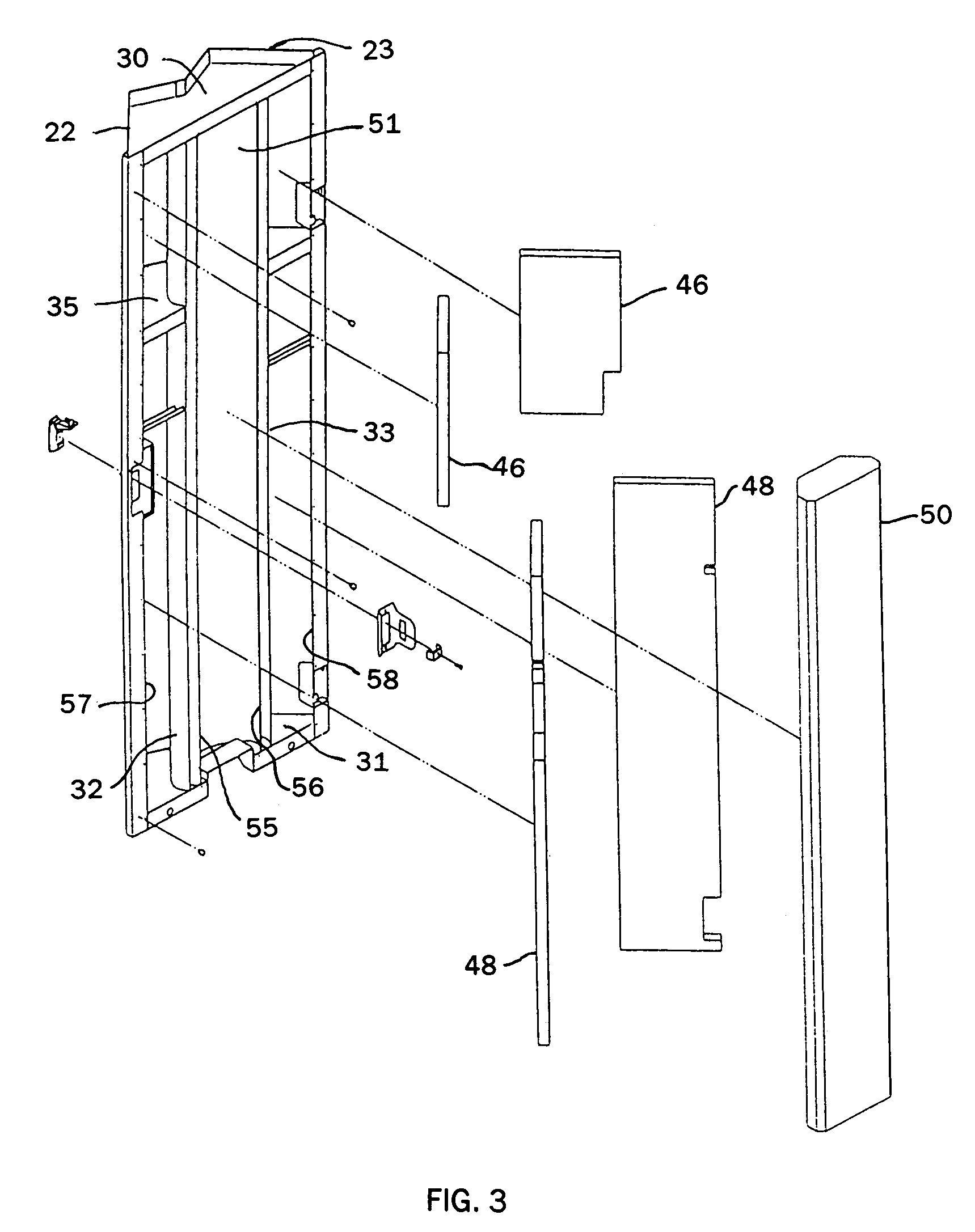
[0015]FIGS. 1 and 2 respectively show outer and inner views of the acoustical door 10 of the present invention. The margins of the door 10 define a substantially planar configuration including the flange portions 12 and 13 of the U-shaped sides 14 and 15 respectively, the connecting top wall flange 18 and the lower wall element flange 19. The door includes panels 22 and 23 which project from the planar door side portions, are angled outward toward one another and define a vertical opening between the panel outer edges 24 and 25. A central column 28 extends vertically between the panels 22 and 23 from the top wall 30 to the lower wall 31. At each lateral side of central column 28 is a scoop or vane 32 and 33. The vanes 32 and 33 also are connected to and extend from the top wall 30 to the lower wall 31. Each of the vanes 32 and 33 are generally parallel to and spaced from the confronting wall surface of the central column 28 with the terminal inward edge turned inward toward the rear...


PUM


Abstract

An acoustic door for an equipment enclosure, such as a rack mount cabinet, also provides a low impedance air flow uniformly delivered across the cabinet opening. A pair of metal panels, with acoustic foam along the rear surfaces, extend angularly outward and toward one another to form an air inlet opening between the outer edges. A central column is positioned between the panels which, in a horizontal section, forms an aerodynamic dome which has a continuously curved sheet metal surface at the front and sides that also captures a core of acoustic foam that is exposed at the rear. A rigid vane is disposed at each lateral side and parallel to the central column to cause air to follow the column surface, deflecting air behind the column and effecting uniform delivery of air flow across the cabinet front opening at the rear opening of the door.

Description

FIELD OF THE INVENTION[0001]The present invention pertains to equipment enclosures and more particularly, to closure doors for such enclosures which enable noise attenuation and provide low impedance air flow through the door.BACKGROUND OF THE INVENTION[0002]Cabinets for rack mounted components must accommodate the need for both air flow and noise attenuation with respect to the cumulative requirements of diverse components that may be selected for mounting within the enclosure. Higher, more concentrated heat loads often increase not only the need for increased cooling air flow, but also the level of noise that must be attenuated. Further, neither the selection of rack mounted components, the positioning of such components within the enclosure, nor the overall cooling or noise attenuation requirements are subject to control by the designer of the equipment enclosure.[0003]Heat loads in rack mounted computer equipment continue to rise with corresponding higher cooling requirements. I...

Claims


Application Information

Patent Timeline
IPC IPC(8): G06F1/20B41J29/08H05K7/20G10K11/16B41J29/10H05K5/03
CPCH05K7/20009
Inventor ANDERL, WILLIAM JAMESO'CONNELL, MICHAEL DESMOND
Owner GOOGLE LLC
Why Eureka
Try Eureka