Sealing device for a turbocharger

a sealing device and turbocharger technology, applied in the direction of positive displacement liquid engines, liquid fuel engines, piston pumps, etc., can solve the problems of reducing the ability of oil to cool the engine, unwanted emissions from the engine, oil or black smoke,

Active Publication Date: 2008-02-26
CATERPILLAR INC
View PDF20 Cites 54 Cited by
  • Summary
  • Abstract
  • Description
  • Claims
  • Application Information

AI Technical Summary

Problems solved by technology

If oil leaks from the bearing housing into the compressor housing or turbine housing, unwanted emissions will likely result from the engine, including oil or black smoke.
On the other hand, if exhaust gases leak from the turbine housing into the bearing housing, known as “blowby,” the exhaust gases may contaminate the oil, therefore reducing the oil's ability to cool the engine and necessitating early replacement of the oil.
Also, blowby can have detrimental effect on the sealing of a crankcase of the engine and on a crankcase closed-circuit ventilation system.
It has become more difficult for seals to eff

Method used


Image

  • Sealing device for a turbocharger
  • Sealing device for a turbocharger
  • Sealing device for a turbocharger

Examples


Embodiment Construction

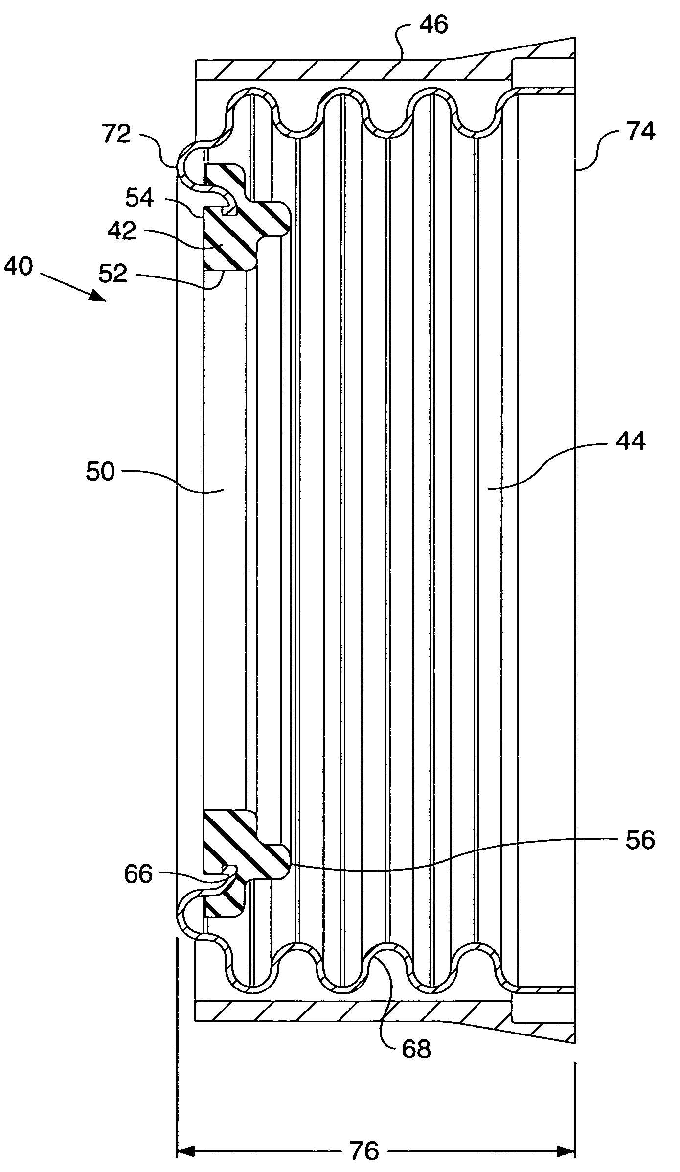
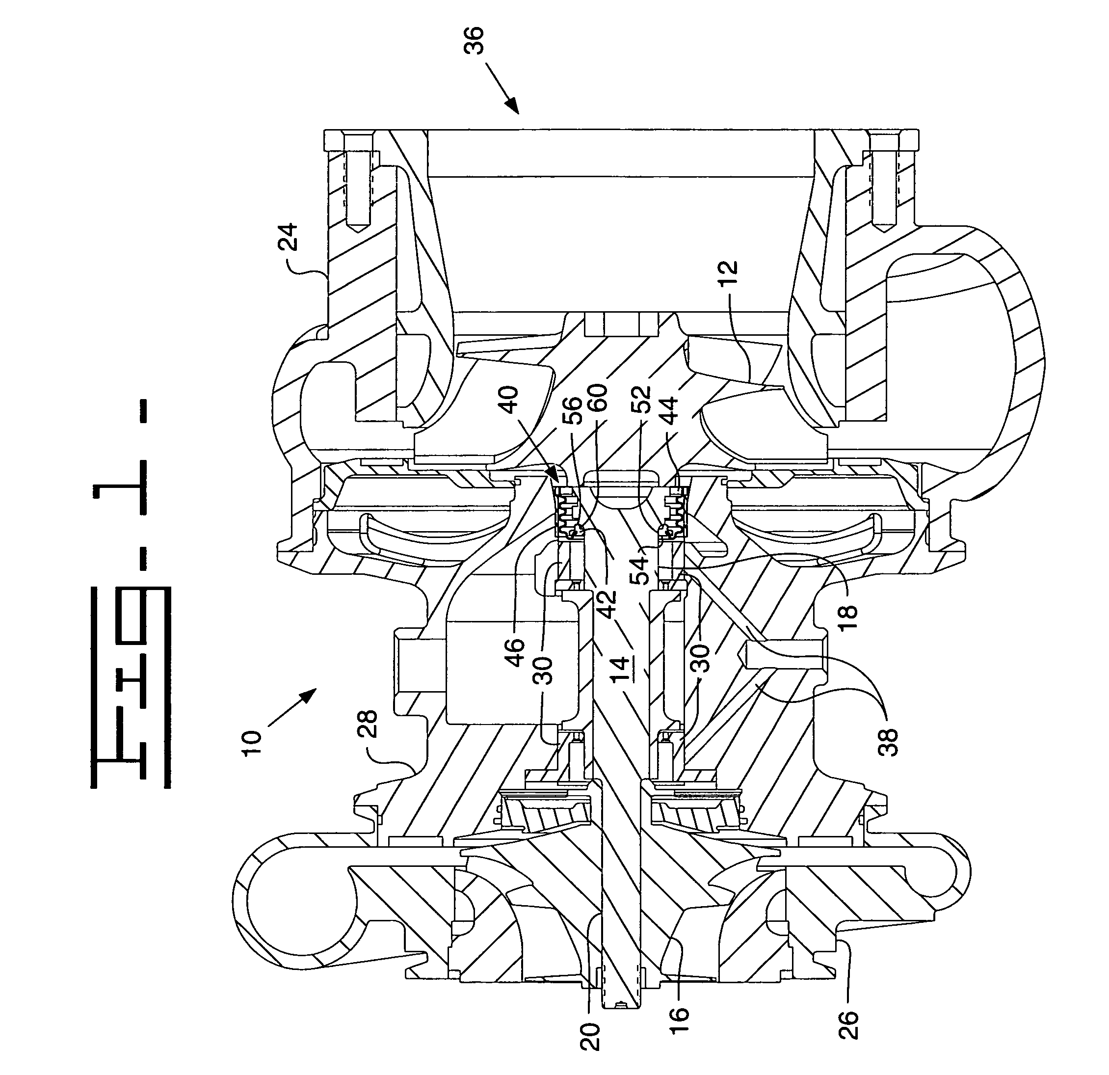
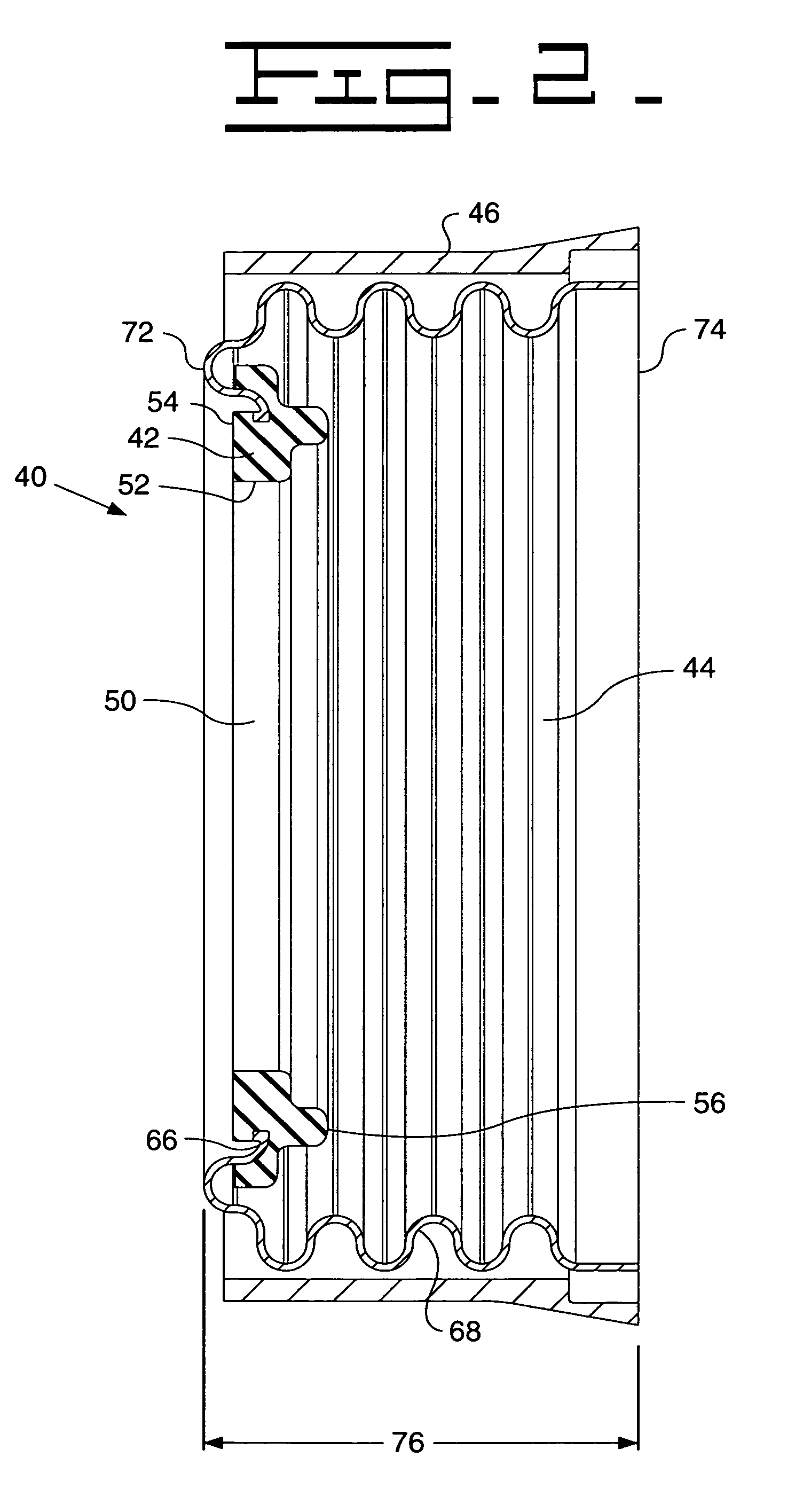
[0014]Referring to FIG. 1, a turbocharger 10 has a turbine wheel 12, a rotatable shaft 14, and a compressor wheel 16. The shaft 14 has a first portion 18 and a second portion 20 spaced from first portion 18. Shaft 14 has an outer surface 22. Turbine wheel 12 is connected to first portion 18 of shaft 14, and compressor wheel 16 is connected to second portion 20 of shaft 14. Turbine wheel 12 is contained within a turbine housing 24, and compressor wheel 16 is contained within a compressor housing 26. A bearing housing 28 is located between and connected to turbine housing 24 and compressor housing 26. Shaft 14 is rotatably connected to bearing housing 28 via bearings 30 contained within bearing housing 28.

[0015]Turbine housing 24 is in fluid communication with exhaust gases of an engine 36. Compressor housing 26 is in fluid communication with intake gases of engine 36. Shaft 14 is lubricated by a fluid, typically oil, that is provided by passages 38 in bearing housing 28. A turbine ho...


PUM


Abstract

A sealing device has a seal ring and a cylindrical bellows portion connected to the seal ring. The cylindrical bellows portion has a corrugated outer surface. A turbocharger utilizing the sealing device has a turbine wheel connected to a shaft and a compressor wheel connected to the shaft. The sealing device is sealingly engaged with the shaft. The sealing device provides a seal between a bearing housing of the turbocharger and either a turbine housing or a compressor housing.

Description

TECHNICAL FIELD[0001]This invention relates generally to sealing devices, and more particularly to a sealing device for use with a turbocharger.BACKGROUND[0002]The use of turbochargers in internal combustion engines is well known. Turbochargers increase the mass of air supplied to the engine thereby enabling the increase of the power output of the engine. In addition, the efficiency of the engine is increased by the turbocharger's utilization of the thermal energy contained in the engine's exhaust gases.[0003]Turbochargers typically have a turbine wheel connected by a rotatable shaft to a compressor wheel. The turbine wheel is contained within a turbine housing and is driven at speeds of up to 200,000 r.p.m. by engine exhaust gases. The turbine wheel operates at a relatively high temperature. The common shaft in turn drives the compressor wheel at a similar speed, forcing air into the engine. The compressor wheel is contained within a compressor housing, and the compressor wheel typ...

Claims


Application Information

Patent Timeline
IPC IPC(8): F16J15/34F04D29/12F01D11/00F01D11/02F16J15/36
CPCF01D11/003F01D11/025F16J15/363F05D2220/40
Inventor O'HARA, STEPHEN J.
Owner CATERPILLAR INC
Why Eureka
Try Eureka