Device and method for compression moulding plastic containers

a technology of plastic containers and compression moulds, which is applied in the direction of dough shaping, manufacturing tools, applications, etc., can solve the problems of difficult compression moulding, explosion in the blow molding phase, and difficult to obtain moulded pieces with particularly precise sizing tolerances, etc., to achieve less expensive, high compression force, and fast response time

Active Publication Date: 2008-02-26
SIPA SOCIETA INDUSTRIALIZZAZIONE PROGETTAZIONE E AUTOMAZIONE SPA
View PDF12 Cites 2 Cited by
  • Summary
  • Abstract
  • Description
  • Claims
  • Application Information

AI Technical Summary

Benefits of technology

[0026]The fact of having a moulding unit with a sliding plunger, at least in the mould-opening and closing direction, with respect to the compression cylinder and the sliding slide, makes it possible and more convenient to use a gas spring system in order to operate the compression cylinder. In fact, the gas spring system is simpler, less expensive, and has faster response times compared to a system using, for example, an oleo or pneumatic system to operate a compression cylinder, while still being able to apply high compression forces. Furthermore, said gas spring makes it possible to unload the moulded workpiece, and in particular to remove the plunger from even a deep-moulded object, at faster speeds than not having a plunger essentially integral with the sliding slide.
[0027]According to the above method, the plunger is detached from the moulded object—which requires the greatest force in the mould-opening phase—using the slide actuators. The slide actuators are also used to keep closed the other parts of the mould during the detachment of the plunger: in this way, it is possible to avoid useless oversizing of the removing actuators. Finally, the mould and its moving members—for example, the lips and the bar of the lips—are stressed optimally and wear better.

Problems solved by technology

This, together with the contraction in volume of the plastic due to cooling in the moulding cavity, makes it difficult to obtain moulded pieces with particularly precise sizing tolerances.
This makes it difficult to compression mould objects such as parisons for processing later through blow moulding, which must have quite precise sizing tolerances and shapes; in fact, filling errors, bubbles, and other geometric irregularities can lead to explosions in the blow-moulding phase.
Furthermore, the shrinkage of the plastic material in the neck and threading areas of the parison can lead to unacceptable appearance problems and problems when screwing the bottle cap.
On the downside, taking into account the shrinkage of the material during compression by increasing the pressure of the plunger makes it harder to remove the object after cooling.
This results in a rather widespread problem where, when compression-moulding objects such as parisons for blow-moulding containers, it is necessary to use notable force in order to extract the plunger, which shapes the internal cavity of the parisons, from the parison after cooling.
Various compression-moulding operations are known for making relatively small plastic objects such as caps for bottles, but these solutions are not immediately applicable for making large or deep plastic containers that generally require high outputs.

Method used


Image

  • Device and method for compression moulding plastic containers
  • Device and method for compression moulding plastic containers
  • Device and method for compression moulding plastic containers

Examples


Embodiment Construction

[0033]In the following description, the terms “continuously operated press” and “continuously operated moulding unit” are used to refer to a device where the moulding cycle is carried out in several moulding cavities with a timing difference between the different cavities: for example, while a moulding cavity is opened to be filled, another unit is closing to compress, and a third unit is opened to remove the moulded workpiece. The terms “sequential press” and “sequential moulding unit” refer to a moulding device where the moulding cycle is executed simultaneously and without timing differences between the different moulding cavities: for example, all the moulding cavities are filled, or closed to compress, or opened to remove the moulded workpieces.

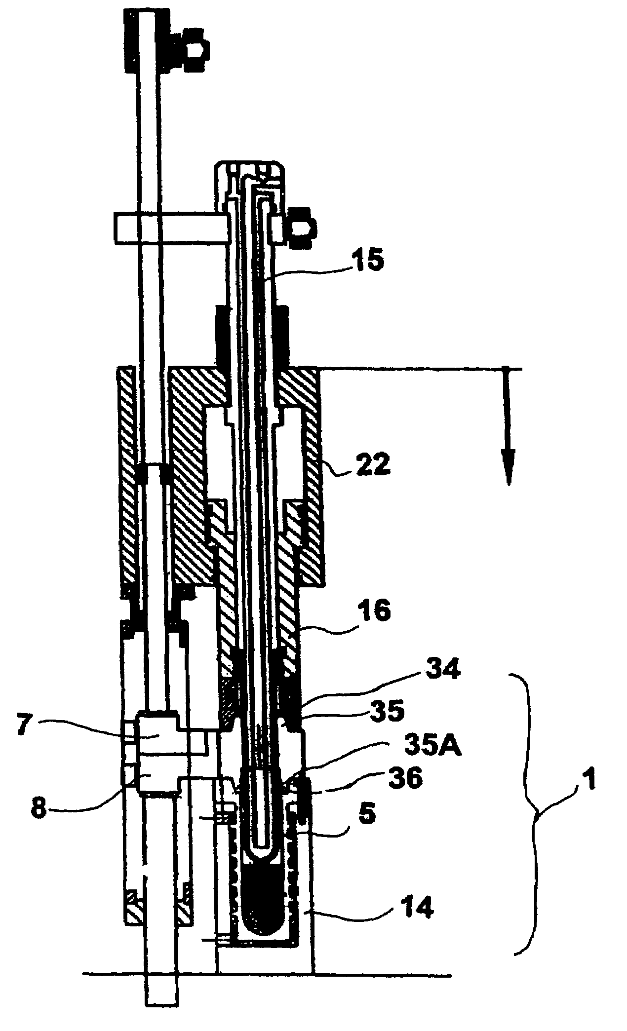
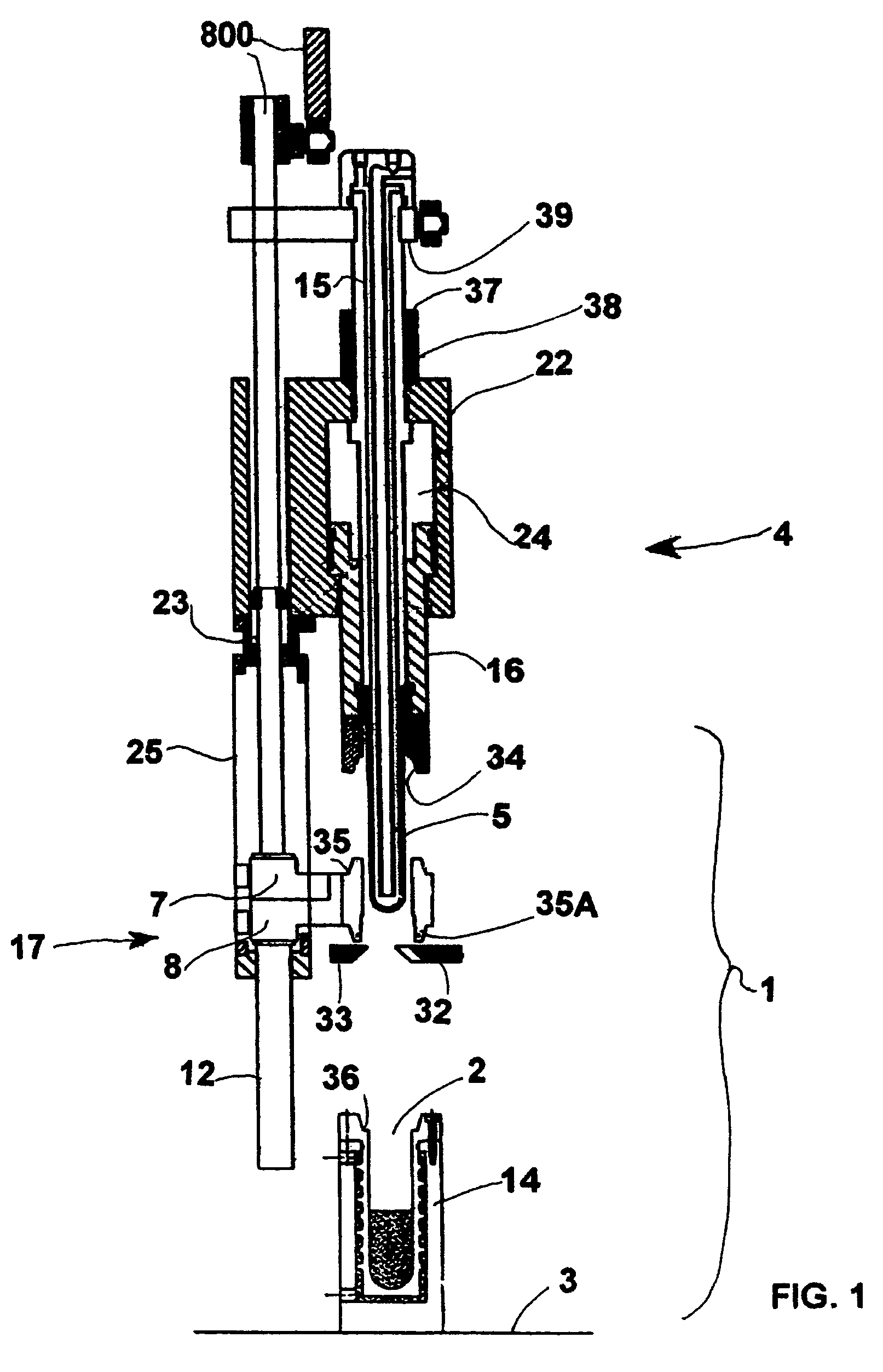
[0034]FIG. 1 shows a mould 1 suitable for compression mould of plastic objects comprising a female mould 14 where there is a moulding cavity 2 for depositing some plastic, for example, PET, PP, PS, PE, PVC, PEN, PBT, etc., in fluid form ...


PUM

PropertyMeasurementUnit
pressureaaaaaaaaaa
compression forcesaaaaaaaaaa
diameteraaaaaaaaaa

Abstract

A compression-moulding press for moulding plastic containers (P) consisting of a moulding cavity formed by a plunger (5), a female mould (14), and two separable lips (7, 8). A cylinder (16) slides inside a sliding slide (22) to keep the lips (7, 8) closed. The plunger (5) slides inside the cylinder (16), with respect to both the cylinder (16) and the slide (22), when moulding the containers (P). Finally, a method for making plastic containers by means of compression moulding using said device is also described.

Description

CROSS REFERENCE TO RELATED APPLICATIONS[0001]The present application is the U.S. national stage application pursuant to 35 U.S.C. §371 of International Application No. PCT / EP03 / 02018, filed Feb. 27, 2003, which application claims benefit of Italian Application No. RM2002A000099, filed on Feb. 27, 2002.FIELD OF THE INVENTION[0002]This invention relates to a device and a method for compression moulding of plastic items. More particularly, it is especially suitable for moulding parisons for making plastic bottles, pots, containers, or similar items through blow moulding.PRIOR ART[0003]The parisons for making blow-moulded containers, especially made of PET, are normally made by means of injection, compression, or extrusion moulding.[0004]Adopting compression moulding for the production of parisons has the following advantages over injection moulding:[0005]Lower moulding temperature and pressure, and, thus, a lower level of residual acetaldehyde in the finished bottle—acetaldehyde also c...

Claims


Application Information

Patent Timeline
Patent Type & Authority Patents(United States)
IPC IPC(8): B29C43/08B29C43/50B29C49/02B29C37/00B29C43/42B29C43/54B29C49/06
CPCB29C37/0017B29C43/08B29C43/42B29C43/50B29C43/54B29C49/061B29C2043/3283B29C2043/5841B29L2001/00B29C2049/023
Inventor ZOPPAS, MATTEO
Owner SIPA SOCIETA INDUSTRIALIZZAZIONE PROGETTAZIONE E AUTOMAZIONE SPA
Why Eureka
Try Eureka