
Hemostatic device including a capsule

a technology of hematoma and capsule, which is applied in the field of hemostasis systems and methods, can solve the problems of inability to accurately place the absorbable material plug directly over the puncture site, the risk of hematoma exists, and the inability to treat patients with substantial amounts

Inactive Publication Date: 2008-02-26
BOSTON SCI CORP +11
View PDF154 Cites 44 Cited by
  • Summary
  • Abstract
  • Description
  • Claims
  • Application Information

AI Technical Summary

Benefits of technology

[0019]According to yet another aspect of the present invention, a system for locating a puncture site in a blood vessel wall and for inhibiting blood loss from the puncture site includes a hemostatic material delivery system having a tube; an elongated member positioned around the tube, a dissolvable distal capsule positioned around the tube, and a hemostatic material located inside the dissolvable distal capsule; and a control tip assembly having a control tip and a control tip body.

Problems solved by technology

In addition, a risk of hematoma exists since bleeding from the vessel may continue beneath the skin until sufficient clotting effects hemostasis.
Further, external pressure to close the vascular puncture site works best when the vessel is close to the skin surface and may be unsuitable for patients with substantial amounts of subcutaneous adipose tissue since the skin surface may be a considerable distance from the vascular puncture site.
The application of an absorbable material such as collagen or a non-absorbable tissue adhesive at the puncture site has several drawbacks including: 1) possible injection of the material into the blood vessel causing thrombosis; and, 2) the inability to accurately place the absorbable material plug directly over the puncture site.
The use of an anchor and plug system addresses these problems to some extent but provides other problems including: 1) complex and difficult application; 2) partial occlusion of the blood vessel by the anchor when placed properly; and 3) complete blockage of the blood vessel or a branch of the blood vessel by the anchor if placed improperly.
Another problem with the anchor and plug system involves reaccess.
Reaccess of a particular blood vessel site sealed with an anchor and plug system is not possible until the anchor has been completely absorbed because the anchor could be dislodged into the blood stream by an attempt to reaccess.
Possible complications of needle biopsy include bleeding at the biopsy site.

Method used


Image

  • Hemostatic device including a capsule
  • Hemostatic device including a capsule
  • Hemostatic device including a capsule

Examples


Embodiment Construction

[0044]Referring to the drawing figures, like reference numerals designate identical or corresponding elements throughout the several figures.

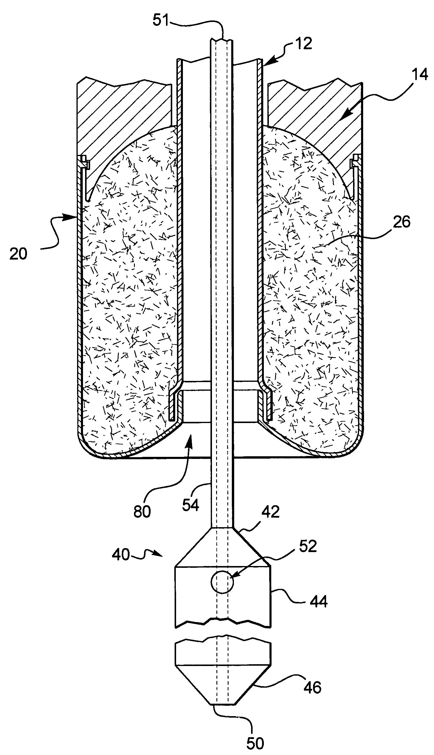
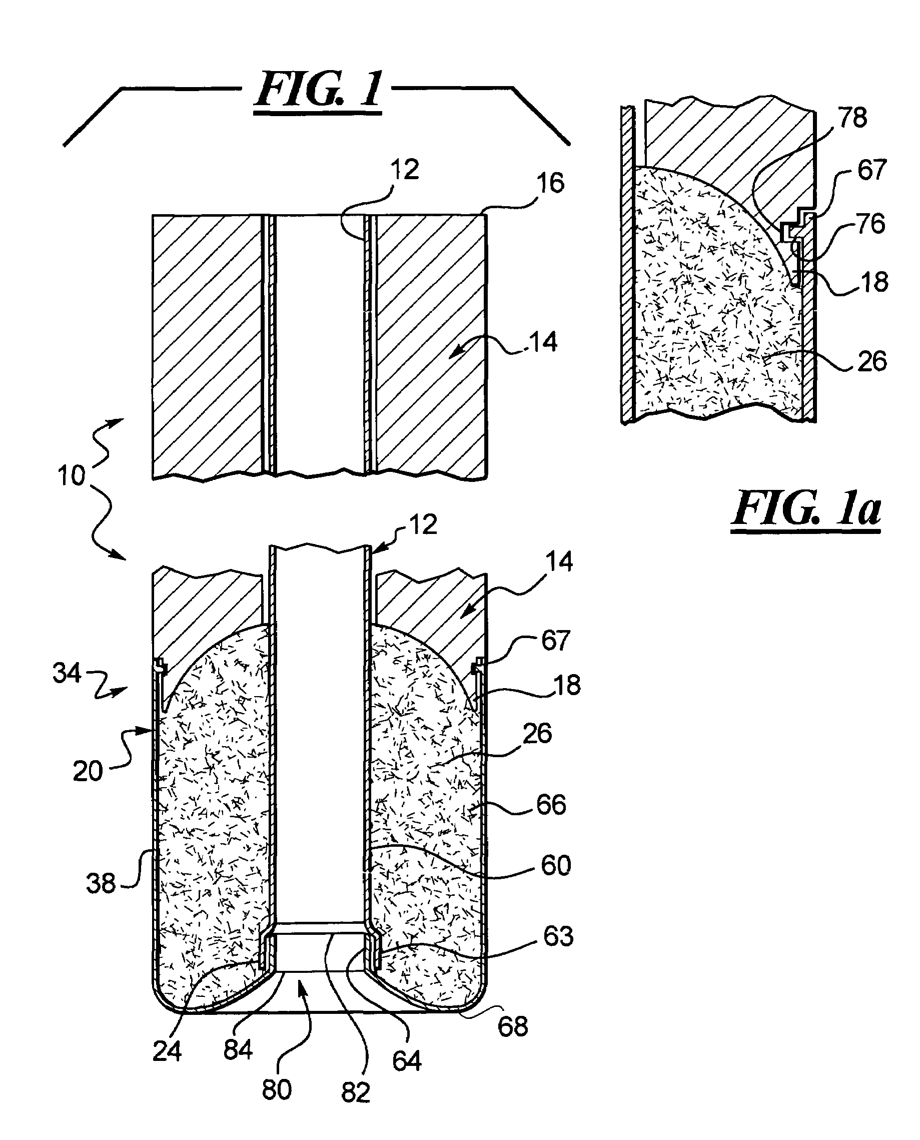
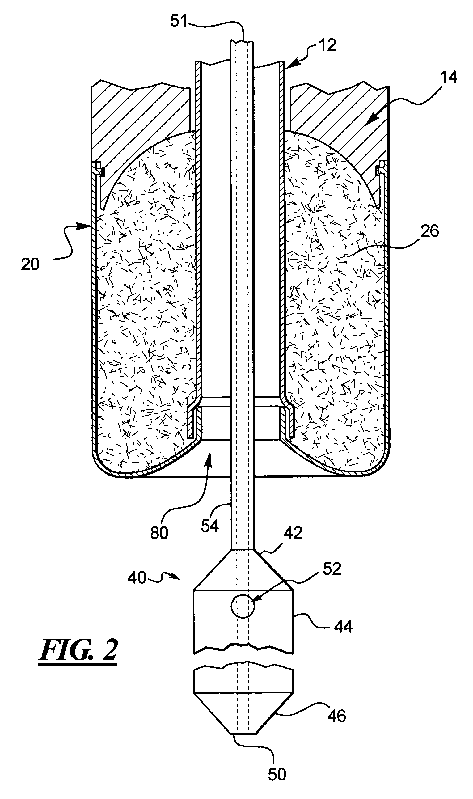
[0045]FIG. 1 illustrates an apparatus 10 for locating a puncture site in a blood vessel wall and for inhibiting blood loss from the puncture site according to the present invention. The apparatus 10 includes a tube 12, an elongated member 14, a dissolvable distal capsule 20, and sponge 26 located inside the dissolvable distal capsule 20. The elongated member 14 has a proximal end 16 and a distal end 18, and is positioned around the tube 12. In a preferred embodiment, the distal end of the elongated member 14 has a substantially concave spherical shape. However, it can be appreciated that the distal end 18 of the elongated member 14 can have any concave shape including a rectangular, a stepped or a flat surface which accommodates the sponge 26 located inside the dissolvable distal capsule 20. At the distal end 18 of the elongated member 14, the ...


PUM

PropertyMeasurementUnit
inner diameteraaaaaaaaaa
thicknessaaaaaaaaaa

Abstract

An apparatus for inhibiting blood loss from a puncture site. The apparatus may include means for locating a puncture site in a blood vessel wall. This apparatus is comprised of a tube and an elongated member that is positioned around the tube. The elongated member includes a proximal end and a distal end. Around the tube is also a dissolvable distal capsule, the distal capsule including a proximal end and a distal end, wherein the proximal end of the distal capsule attaches to the distal end of the elongated member. Inside the distal capsule is hemostatic material such as a sponge.

Description

RELATED APPLICATION[0001]This application is a Continuation in Part of prior co-pending U.S. patent application Ser. No. 10 / 287,922, titled “Apparatus and Method for Inhibiting Blood Loss”, filed Nov. 4, 2002.BACKGROUND OF THE INVENTION[0002]1. Field of the Invention[0003]The invention relates to hemostasis systems and methods for blood vessel puncture sites, biopsy tracts and other puncture wound sites.[0004]2. Brief Description of the Related Art[0005]A large number of diagnostic and interventional procedures involve the percutaneous introduction of instrumentation into a vein or artery. For example, coronary angioplasty, angiography, atherectomy, stenting of arteries, and many other procedures often involve accessing the vasculature through a catheter placed in the femoral artery or other blood vessel. Once the procedure is completed and the catheter or other instrumentation is removed, bleeding from the punctured artery must be controlled.[0006]Traditionally, external pressure i...

Claims


Application Information

Patent Timeline
Patent Type & Authority Patents(United States)
IPC IPC(8): A61B17/08A61D1/00A61B17/00A61B17/04A61B17/34A61FA61L31/04A61L31/14
CPCA61B17/0057A61L31/045A61L31/146A61L31/148A61B2017/00004A61B2017/00654A61B2017/00672A61B2017/00898A61B2017/0406A61B2017/3419A61B2017/3482A61L2400/04
Inventor ASHBY, MARKTRAN, TIN TRONG
Owner BOSTON SCI CORP
Learn More