Joint assembly of a car windshield wiper arm

a technology of windshield wiper arm and joint assembly, which is applied in the direction of couplings, vehicle cleaning, manufacturing tools, etc., can solve the problems of easy inadvertent drop, windshield or hood lacquer damage,

Inactive Publication Date: 2008-03-04
HUANG SHIH HSIEN
View PDF13 Cites 15 Cited by
  • Summary
  • Abstract
  • Description
  • Claims
  • Application Information

AI Technical Summary

Benefits of technology

[0009]The main object of the present invention is to provide a joint of a car windshield wiper arm, which comprises an upper cover body and a chassis; Exploiting the round groove cut of the upper cover body and the fixing pivot on the chassis being intimately engaged each other to serve as a pivot, as well as the elastic upright embed hook of the upper cover body and the insetting hole on the chassis being inset each other, hence, the drawback of hurting windshield caused by said wiper being dropped off during replacement procedure of worn wiper by new one can be avoided.

Problems solved by technology

However, during the replacement of worn wiper by new one, the aforesaid jointer of said trapezohedron shaft 2 has the drawback of being easy to inadvertently drop and hurt the windshield or the lacquer of the hood.

Method used


Image

  • Joint assembly of a car windshield wiper arm
  • Joint assembly of a car windshield wiper arm
  • Joint assembly of a car windshield wiper arm

Examples


Embodiment Construction

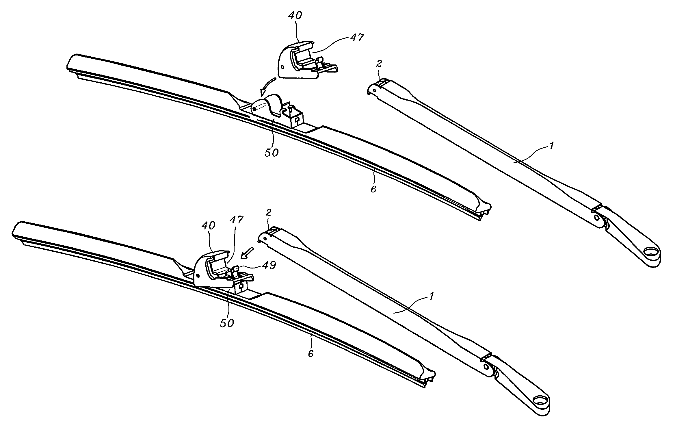
[0038]Referring to FIG. 13 through FIG. 17, the present invention, joint assembly of a car windshield wiper arm comprises:

[0039]an upper cover body 4O, having a front side 41, a top side 42, a bottom side, a left side 43, a right side 44, a rear end 45, and a solid core 46 between said left side 43 and said right side 44; wherein, a left groove cut 462 is formed upward from said bottom side between said left side 43 and said solid core 46, and a right groove cut 463 is formed upward from said bottom side between said right side 44 and said solid core 46 (as shown in FIG. 14); a round groove cut 464 with V-shaped cross-section is concaved near said front side 41; a trapezohedron receptacle 47 is formed horizontally across a rear of said solid core having a rear facing opening; said left side 43 and right side 44 respectively including a parallel and symmetrical left rib 431 and right rib 441, said left rib 431 and said right rib 441 extending from below said trapezohedron receptacle ...


PUM


Abstract

An upper cover body has left and right grooves between a solid core and left and right sides; a round groove near a front side; a rear facing receptacle across a rear of the solid core; the left and right sides including left and right ribs extending to the rear end encompassing a hollow socket; an elastic embed hook on the rear end corresponding with the receptacle and having a forward facing nose. A chassis has a bottom plate, left and right plates extending upward from respective sides of the bottom plate, and a rear plate; a fixing hole in the bottom plate; an upright curbing plate at the rear end of the bottom plate; a front horizontal fixing pivot between the left and right plates; an upright hollow plug encompassed by the left, right, and rear plates; an insetting hole centered in the rear plate.

Description

FIELD OF THE PRESENT INVENTION[0001]The present invention relates to a joint assembly of a windshield wiper arm, more particularly being contrived for the wiper arm with trapezohedron shaft. Hence, the drawback of hurting windshield caused by the wiper dropping off during replacement procedure of worn wiper by new one can be avoided.BACKGROUND OF THE PRESENT INVENTION[0002]Presently, the types in head of windshield wiper arm are many in variety. Different type design of wiper arm head must be coordinated with its exclusive jointer to enable securely joint each other. Such as USA issued patents U.S. Pat. No. 6,516,491, U.S. Pat. No. 6,643,889, U.S. Pat. No. 6,668,419, U.S. Pat. No. 6,810,556, U.S. Pat. No. 6,836,927, U.S. Pat. No. 6, 836,926, U.S. Pat. No. 6,874,195, U.S. Pat. No. 6,886,213 and U.S. Pat. No. 6,904,639 as well as USA published patents US2004 / 0025280 and US2004 / 0098821, all disclosed their different types of wiper arm head in association with its exclusive jointers. In...

Claims


Application Information

Patent Timeline
Patent Type & Authority Patents(United States)
IPC IPC(8): B60S1/40
CPCB60S1/3848B60S1/3867B60S1/4038B60S1/4041Y10T403/60Y10T403/59Y10T403/18Y10T403/606B60S1/4048
Inventor HUANG, SHIH-HSIEN
Owner HUANG SHIH HSIEN
Why Eureka
Try Eureka