

Inertial sensor and combined sensor therewith
a sensor and sensor combination technology, applied in the field ofinertial sensors, can solve the problems of inability to actively diagnose and abnormality in the sensor itsel
- Summary
- Abstract
- Description
- Claims
- Application Information
AI Technical Summary
Benefits of technology
Problems solved by technology
Method used
Image

Examples
first embodiment
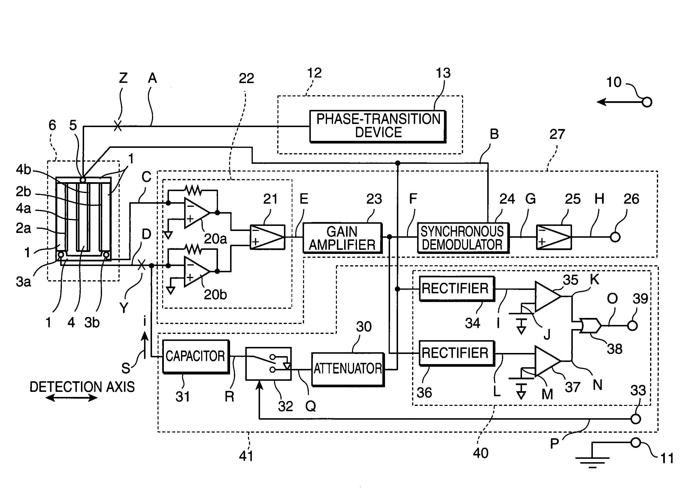
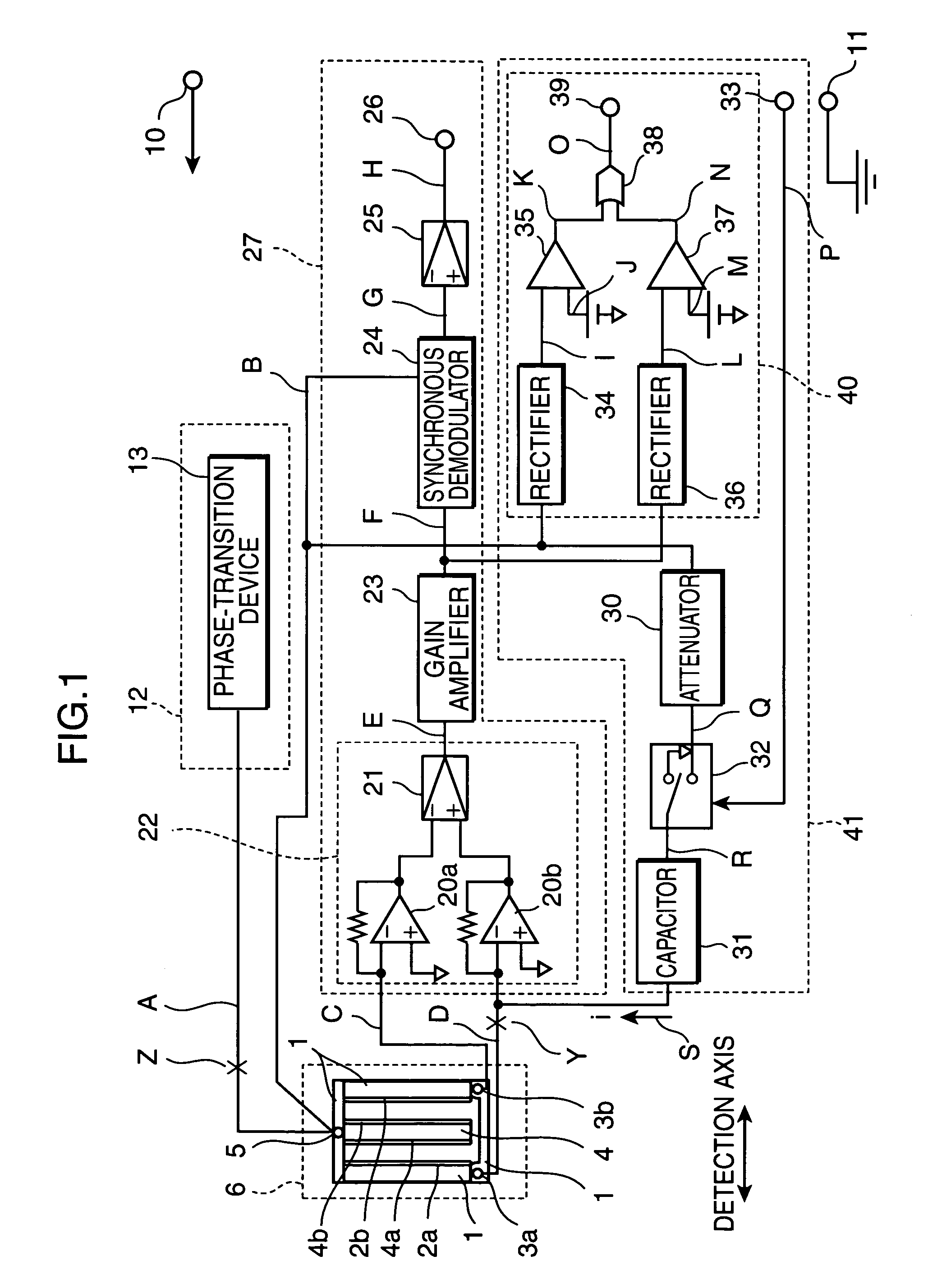
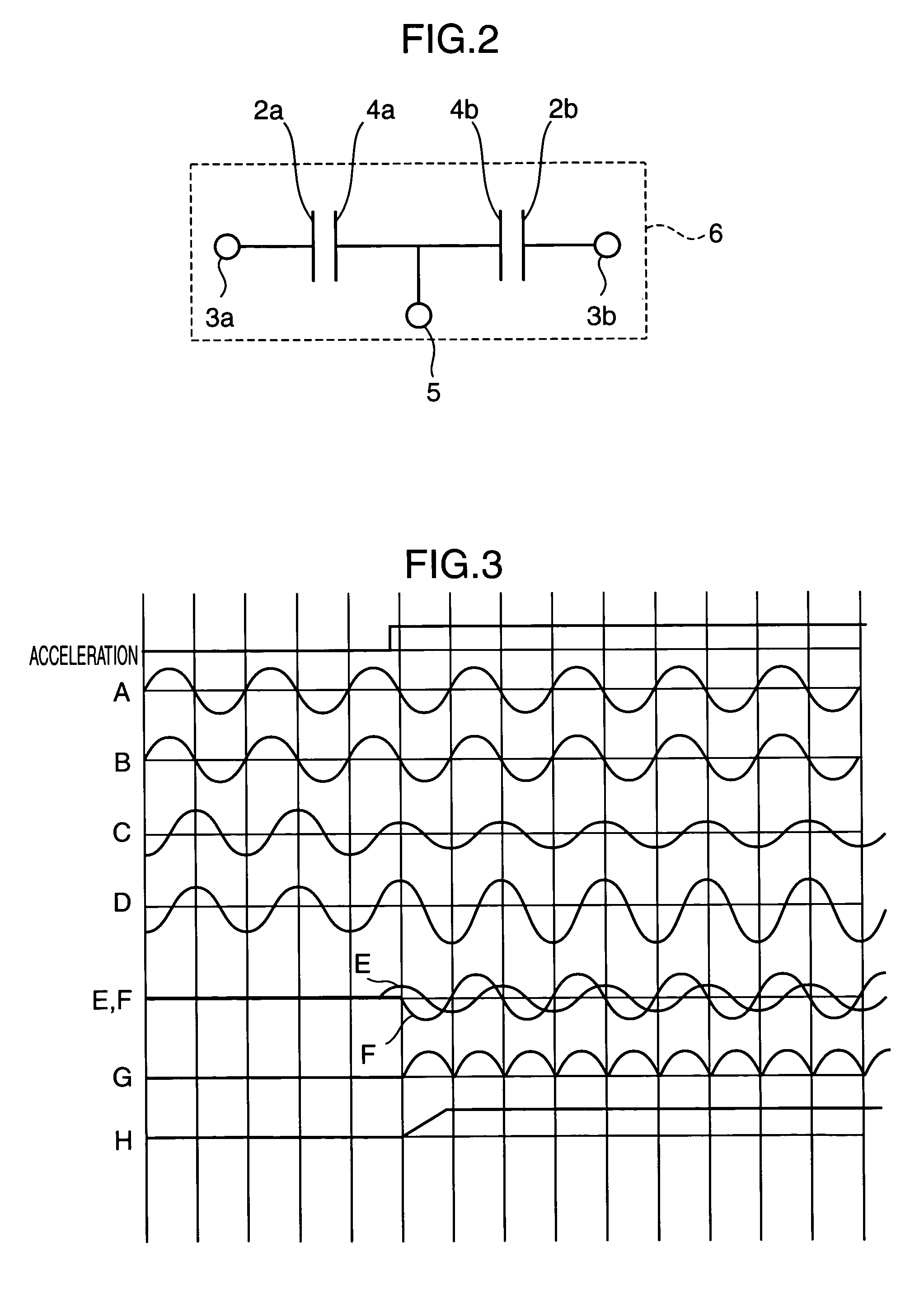
[0028]FIG. 1 is a block diagram, showing an inertial sensor according to a first embodiment of the present invention. FIG. 2 is an equivalent circuit diagram, showing a detecting element which configures the inertial sensor. FIG. 3 is a wave form chart, showing an operation of each portion of the inertial sensor. FIG. 4 is a wave form chart, showing an operation of each portion of the inertial sensor, in the case where it is disconnected at a point Y and a point Z. FIG. 5 is a wave form chart, showing an operation of each portion of the inertial sensor, when a diagnostic request signal is given from the outside to the inertial sensor.
[0029]The inertial sensor shown in FIG. 1 includes: a detecting element 6; a drive circuit 12; a detection circuit 27; and a self-diagnosis circuit 41. The detecting element 6 is provided with: a fixed portion 1; first and second detection electrodes 2a, 2b; first and second output terminals 3a, 3b; a movable portion 4; first and second movable electrod...
second embodiment
[0062]FIG. 6 is a side view of a detecting element of an inertial sensor according to a second embodiment of the present invention, showing its configuration. According to this embodiment, a drive circuit, a detection circuit, or a self-diagnosis circuit is configured in the same way as according to the above described embodiment. Hence, their figure and description are omitted, and thus, only different parts are described in detail.
[0063]In the detecting element shown in FIG. 6, a first and second detection electrodes 51, 52 are provided in a fixed portion 50. A movable electrode 56 is provided in a movable portion 53, so that it faces the first and second detection electrodes 51, 52. The first and second detection electrodes 51, 52 are placed at a predetermined distance on one and the same plane of the fixed portion 50. The movable electrode 56 is placed, at a predetermined distance from each of the first and second detection electrodes 51, 52, and opposite to them. The AC-bias si...
third embodiment
[0068]FIG. 7 is a block diagram, showing an inertial sensor according to a third embodiment of the present invention. In this embodiment, the parts which have the same configuration as those in the above described first and second embodiments are given their identical reference numerals. Hence, their detailed description is omitted, and thus, only different parts are described in detail.
[0069]As shown in FIG. 7, first and second movable electrodes 58, 59 are provided at a predetermined distance on one and the same plane of the movable portion 53 and oppositely to the first and second detection electrodes 51, 52, respectively. A first resistor 60 is inserted between the drive circuit 12 and the second movable electrode 59. It is used to set a predetermined AC-bias-signal-voltage value which is different from the AC-bias signal voltage V. A second resistor 62 is connected to a point 61 at which the second movable electrode 59 and the first resistor 60 are connected. A circuit breaker ...
PUM
 Abstract
Description
Claims
Application Information