System and method for measuring plantar foot pressure

a plantar foot and pressure measurement technology, applied in the field of system and method for measuring plantar foot pressure, can solve the problem of expensive methods and achieve the effect of preventing plantar foot ulceration

Active Publication Date: 2008-03-04
KANTRO SCOTT
View PDF11 Cites 22 Cited by
  • Summary
  • Abstract
  • Description
  • Claims
  • Application Information

AI Technical Summary

Benefits of technology

[0007]The present invention overcomes the drawbacks associated with the prior art foot pressure measuring systems and provides for a low-cost, efficient and reliable means for measuring plantar foot pressure for detecting “high-pressure” areas in order to prevent plantar foot ulcerations.

Problems solved by technology

Many methods have been developed in the past to measure plantar foot pressure, however, these methods are often costly and require special training to operate the necessary devices.

Method used


Image

  • System and method for measuring plantar foot pressure
  • System and method for measuring plantar foot pressure
  • System and method for measuring plantar foot pressure

Examples


Embodiment Construction

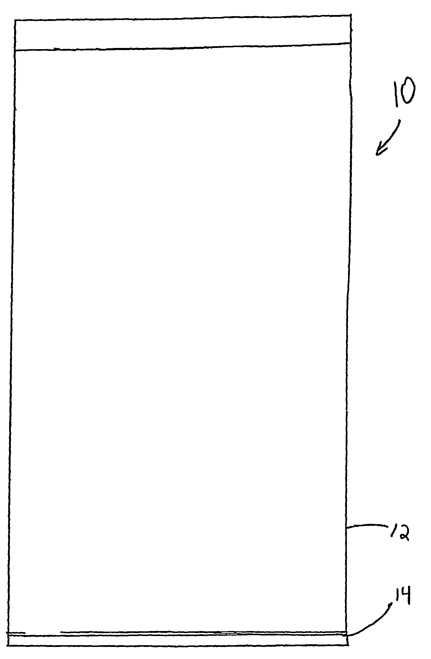
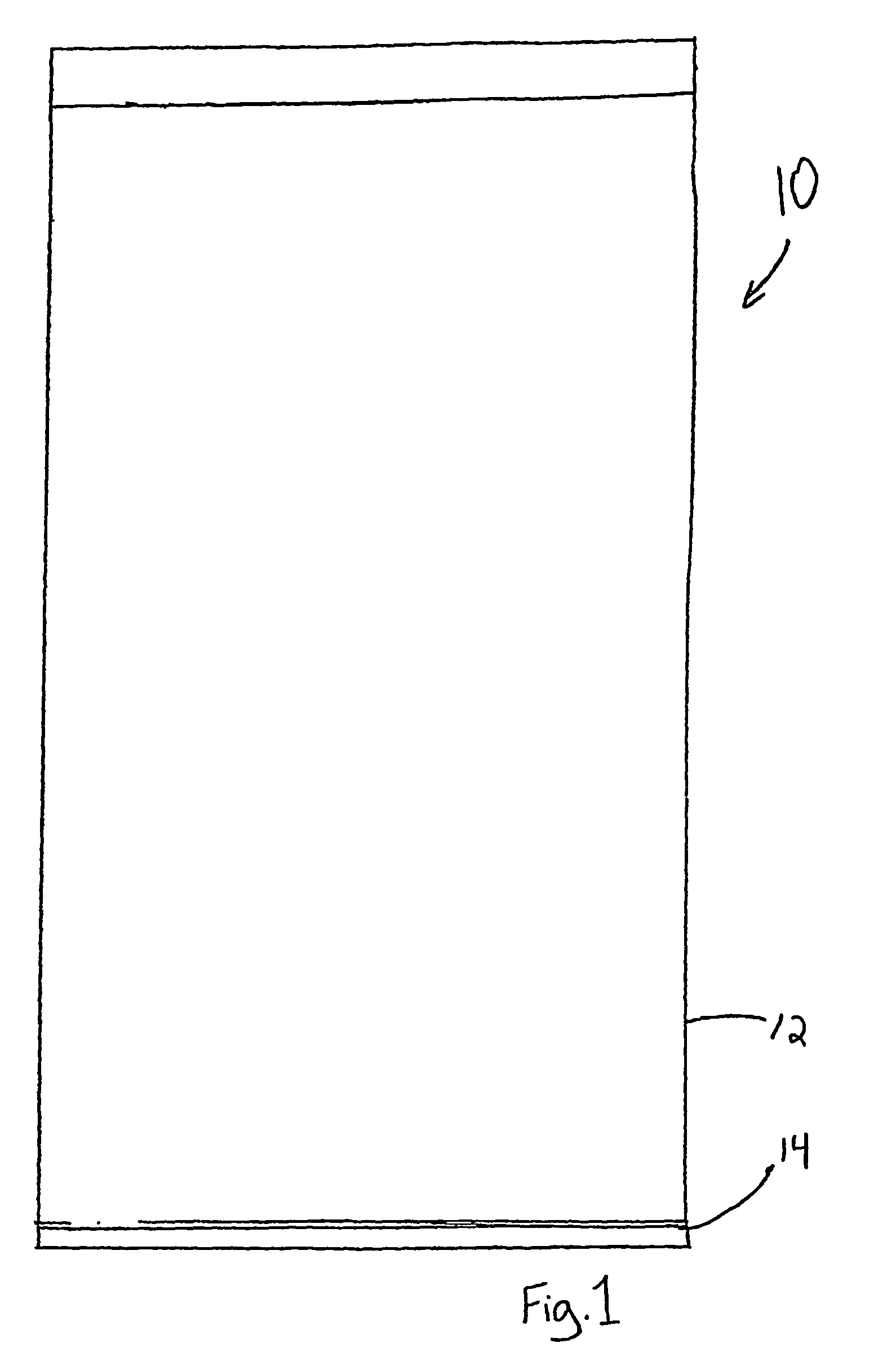
[0017]The present invention maintains a pressure measuring device 10 for measuring the plantar foot pressure of a patient. A calibration card 50 is used in conjunction with pressure measuring device 10 in order to discern the measured pressures.

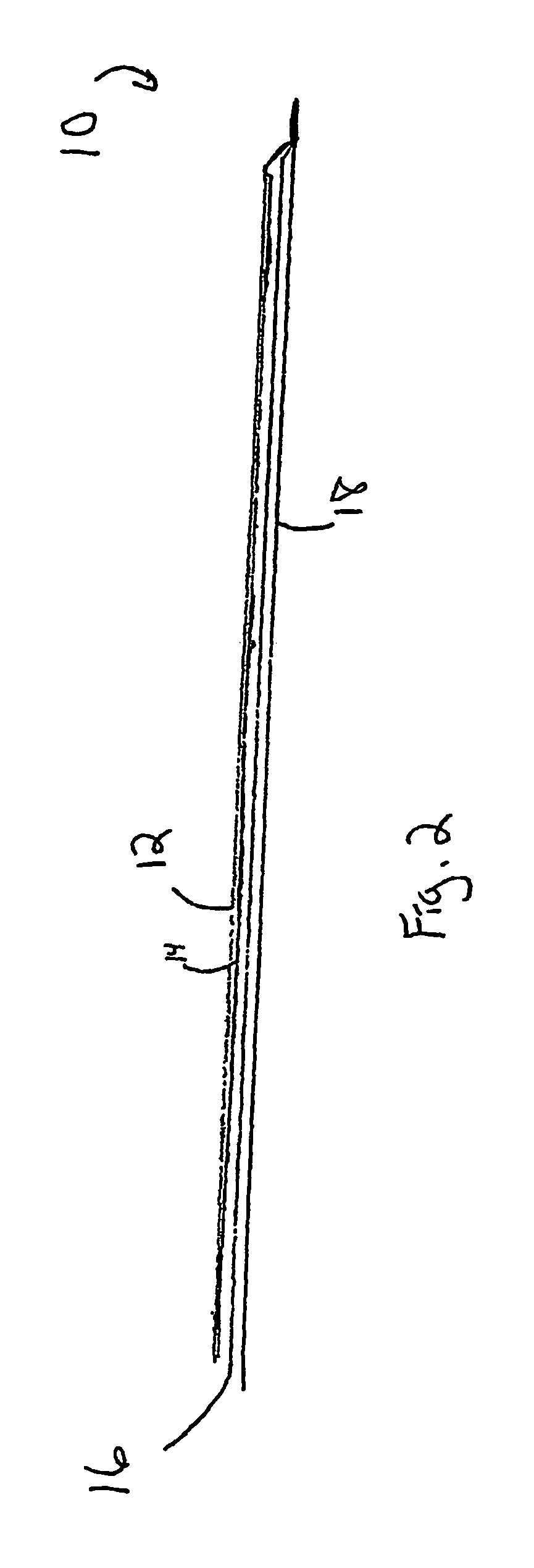
[0018]In one embodiment of the present invention as illustrated in FIGS. 1 and 2, pressure measuring device is substantially rectangular in shape. Any similar shape may be used that is adequate to cover the entire underside of the patient's foot. A clear cover sheet 12 is provided that forms the top layer of the measuring device 10. The top surface of cover sheet 12 is smooth and is configured to provide a place for the patient to place their foot during testing.

[0019]Cover sheet 12 is provided with a sticky underside, configured to capture and adhere a certain portion of the pressure sensitive ink used during testing. A cover sheet backing layer 14 is provided such that the sticky underside of cover sheet 12 does not come into contact with t...


PUM

PropertyMeasurementUnit
sizeaaaaaaaaaa
pressureaaaaaaaaaa
color densityaaaaaaaaaa

Abstract

A measuring device (10) is used for generating an imprint of a patient's foot. The imprint includes a first set of at least two differentiable color density markings. The first set of differentiable density markings each correspond to a different pressure exerted on the measuring device by different areas of the patient's foot. A calibration card (50) is provided with an indicia including a set of at least two differentiable density markings. Each differentiable density marking in the second set of differentiable density markings on the calibration card has a viewing opening (56) disposed within, such that when the viewing openings in the calibration card are placed over the imprint of the patient's foot, the first set of different density markings from the imprint are viewable through the viewing openings so that they are readably comparable to the second set of differentiable density markings in the indicia on the calibration card.

Description

RELATED APPLICATIONS[0001]This application is a 371 of PCT / US03 / 39321.[0002]This application is related to and claims the benefit of priority from U.S. Provisional Patent Application No. 60 / 433,282, filed on Dec. 13, 2002, the entirety of which is incorporated herein by reference.FIELD OF THE INVENTION[0003]The present invention is related to a system and method for measuring plantar foot pressure. More specifically, the present invention is directed to a system and method for low-cost, accurate plantar foot pressure measurement.BACKGROUND OF THE INVENTION[0004]It is well known that plantar ulcerations, commonly found in diabetic persons, develop in the feet over areas of high pressure. In these situations, the ulcerations can be associated with motor neuropathy, foot deformation, limited joint mobility, callus formation, even foot amputation. It is also known that high-pressure areas have been clinically proven as indicators of the likelihood of development of these plantar foot ul...

Claims


Application Information

Patent Timeline
Patent Type & Authority Patents(United States)
IPC IPC(8): G01L1/26G01L5/04A61B5/103G01D7/00G01M99/00G01L1/06G01L1/22G01L1/24
CPCA61B5/1036G01L1/06G01L1/247
Inventor KANTRO, SCOTT
Owner KANTRO SCOTT
Why Eureka
Try Eureka