Projectile firing device using liquified gas propellant

a technology of projectile and propellant, which is applied in the direction of compressed gas guns, nailing tools, white arms/cold weapons, etc., can solve the problems of high energy transfer efficiency of explosive materials to projectiles, large thermal energy (heat) emissions, and noise that can be easily detected with and without aid, and the arrangement is not suitable for high-speed weapons of the type used for military purposes

Inactive Publication Date: 2008-03-04
POLY SYST PTY LTD
View PDF13 Cites 804 Cited by
  • Summary
  • Abstract
  • Description
  • Claims
  • Application Information

AI Technical Summary

Problems solved by technology

There are a number of disadvantages associated with such conventional weapons.
Firstly, they are highly inefficient in energy transferral from the explosive material to the projectile velocity of the ammunition.
A number of other disadvantages associated with conventional guns and rifles are the emission of large amounts of thermal energy (heat) and noise that can be easily detected with and without the aid of conventional detection equipment.
However, such arrangements are not suitable for high velocity weapons of the type used for military purposes.
However, these heating arrangements suffer from the disadvantage that they do not ensure reliable repeated firing of a gun over a wide range of cold ambient temperatures.

Method used


Image

  • Projectile firing device using liquified gas propellant
  • Projectile firing device using liquified gas propellant
  • Projectile firing device using liquified gas propellant

Examples


first embodiment

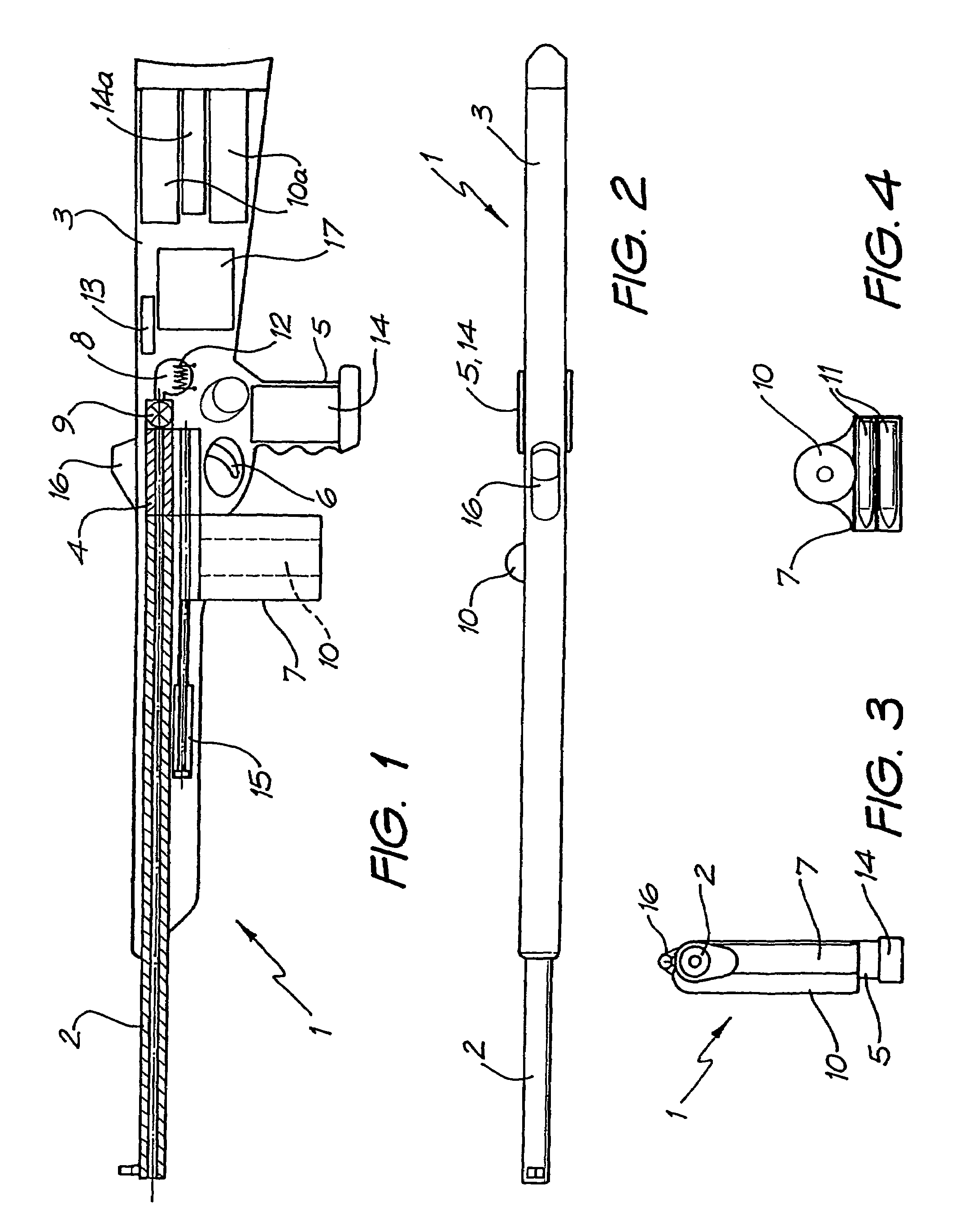
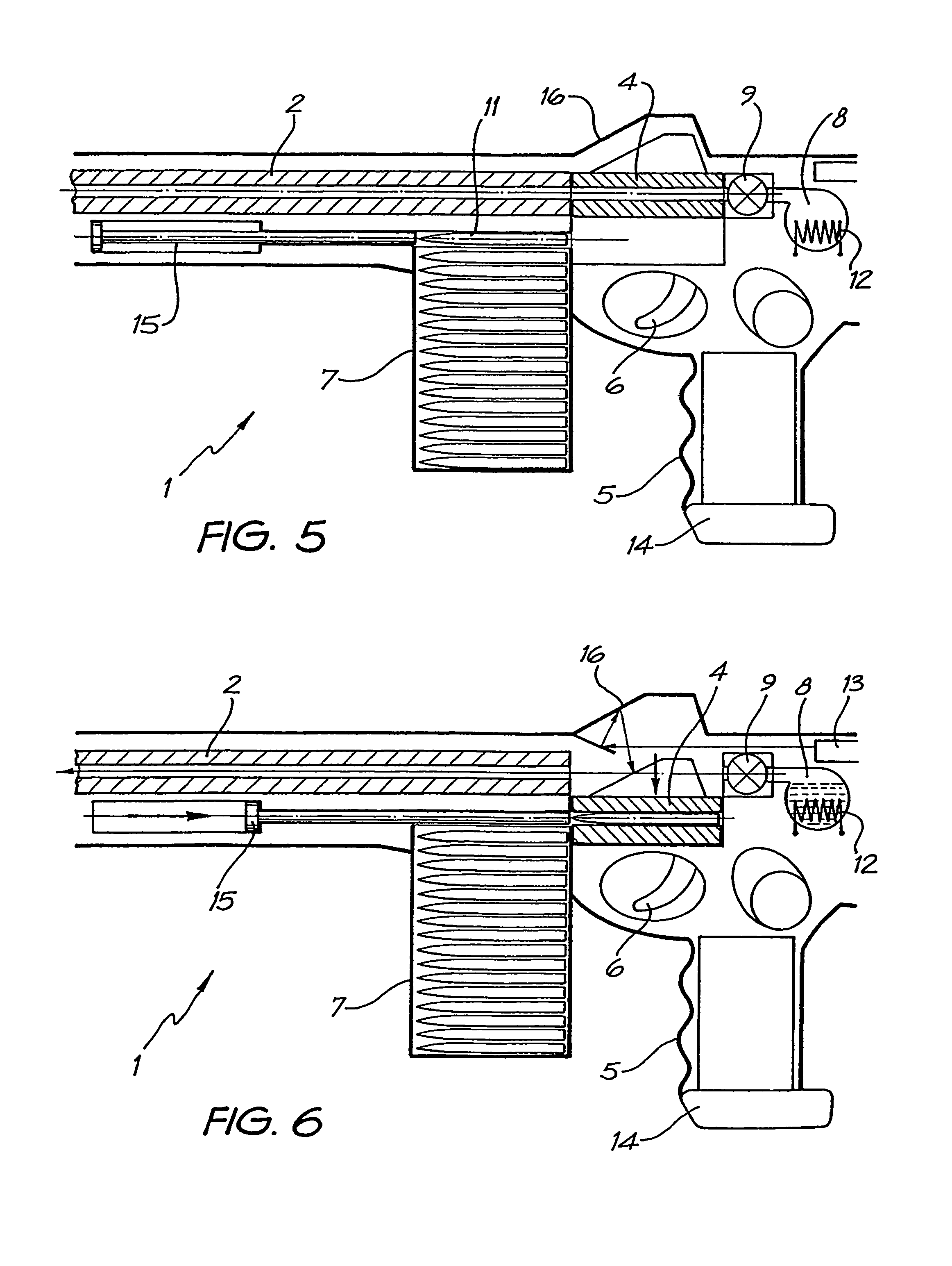
[0052]FIGS. 1 to 4 depicts a rifle 1 and its ammunition in accordance with a projectile firing device of the present invention. In a similar manner to conventional rifles, rifle 1 has a rifled barrel 2, stock 3, breech 4, pistol grip 5, trigger mechanism 6 and removable ammunition magazine 7.

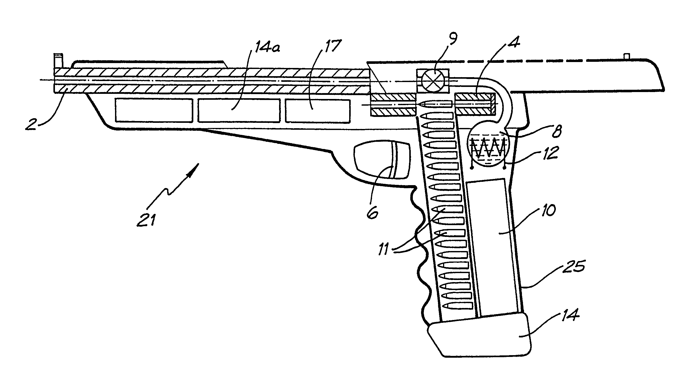
[0053]Rifle 1 also has a high-pressure chamber 8 in fluid communication with barrel 2, via a gas lock off-valve 9. A canister 10 containing liquid carbon dioxide (CO2) is integrally housed within magazine 7.

[0054]The rifle 1 fires an ammunition projectile 11 loaded into breech 4 in the following manner. The liquid CO2 contained in canister 10 is the propellant used to fire projectile 11. Liquid CO2 is introduced into chamber 8 from canister 10. The fluid communication means between canister 10 and chamber 8 has been omitted from the figures for the purpose of clarity. The liquid CO2 in chamber 8 is heated by a heating element 12 that is powered by an electrical battery power supply 14 housed wit...

second embodiment

[0075]FIGS. 9 and 10 depict a pistol 21 in accordance with a projectile firing device of the present invention. The pistol 21 like the rifle 1 fires an ammunition projectile 11 loaded into breech 4. In particular, pistol 21 also contains a liquid CO2 canister 10 that is loaded into the pistol grip 25 along with magazine 7 containing projectiles 11. In a like manner to that of rifle 1, liquid CO2 contained within canister 10 is introduced into chamber 8 and may be heated by a heating element 12 that is powered by an electrical battery power supply 14 housed within the body of pistol 21. The dispatch of projectiles 11 occurs in a similar manner to that in rifle 1 in that the liquid CO2 is induced to change its state from a liquid to a “highly dense” gas.

[0076]FIG. 11 depicts an artillery / naval gun 31 in accordance with a third embodiment of a projectile firing device of the present invention. The gun 31, like that of rifle 1 of the first embodiment utilizes liquid CO2 which is introdu...

fifth embodiment

[0079]FIG. 16 to 23, depict a mortar launcher 51 and mortar projectiles 11c in accordance with a projectile firing device of the present invention. The mortar launcher 51 may typically be constructed of an aluminum / KEVLAR compose and comprise a high energy output battery pack 14b, electronic inclinometer, GPS and compass display 16b for accurate targeting, and a lightweight adjustable stand 52. Up to 70% weight saving can be achieved by using the aluminum / KEVLAR composite materials to provide infantry with a more mobile mortar support facility. The tubular body of launcher 51 has an aluminum honeycomb central section 63“sandwiched” between an inner KEVLAR section 64 and an outer KEVLAR section 62.

[0080]The mortar projectile 11c is a high explosive pre-shrapnel projectile comprising a front section 53 and a rear section 54. The front section 53 may be manufactured from steel containing high explosive 55 surrounded by pre-fragmented steel particles 56 (which can be replaced by magnesi...


PUM


Abstract

Rifle (1) comprises barrel (2) and loading means (15) for introducing a projectile from magazine (7) into breech (4). The projectile is propelled by a compressed gas propellant initially stored as a liquid in canister (10). The liquid is heated to a super critical state in chamber (8) by heating element (12) to induce a phase change such that the liquid becomes a highly dense gas. The phase change from liquid to gas provides the energy required to expel the projectile at high velocity from rifle (1), regardless of the ambient temperature. The propellant is preferably CO2 which is heated to 31.06° C. Rifle (1) produces minimal noise and no heat signature, making it suitable for military and stealth purposes. A pistol and launchers for grenades or mortar bombs are also disclosed. Another version can launch low earth orbit satellites or payloads.

Description

TECHNICAL FIELD[0001]The present invention relates to a projectile firing device, and more particularly to such a device that uses a propellant that is initially stored in a liquid phase and undergoes a phase change to a “highly dense” gas to effect propulsion of the projectile. The projectile firing device may in number of embodiments relate to a weapon such as a gun, rifle, pistol, grenade or mortar launcher. In another embodiment the projectile firing device may be used as a low earth orbit satellite-launch device.BACKGROUND[0002]Conventional weapons such as rifles and guns use gunpowder or cordite as the explosive material to propel ammunition. Such explosive materials provide a violent expansion of gases and the liberation of relatively large amounts of thermal energy to achieve propulsion of the ammunition. There are a number of disadvantages associated with such conventional weapons. Firstly, they are highly inefficient in energy transferral from the explosive material to the...

Claims


Application Information

Patent Timeline
Patent Type & Authority Patents(United States)
IPC IPC(8): F41B11/00B25C1/00F41B11/57F41B11/62
CPCF41B11/57F41B11/62F41B11/71
Inventor WEBB, ROGER CLYDE
Owner POLY SYST PTY LTD
Why Eureka
Try Eureka