
Multiple position leg rest mechanism

a leg rest and multi-position technology, applied in the field of furniture members, can solve the problems of increasing mechanism noise, undue wear, and difficult to ensure the continuous application of lubricant, and achieve the effect of reducing the noise of the mechanism and limiting the noise generated

Inactive Publication Date: 2008-03-04
LA-Z-BOY
View PDF6 Cites 22 Cited by
  • Summary
  • Abstract
  • Description
  • Claims
  • Application Information

AI Technical Summary

Benefits of technology

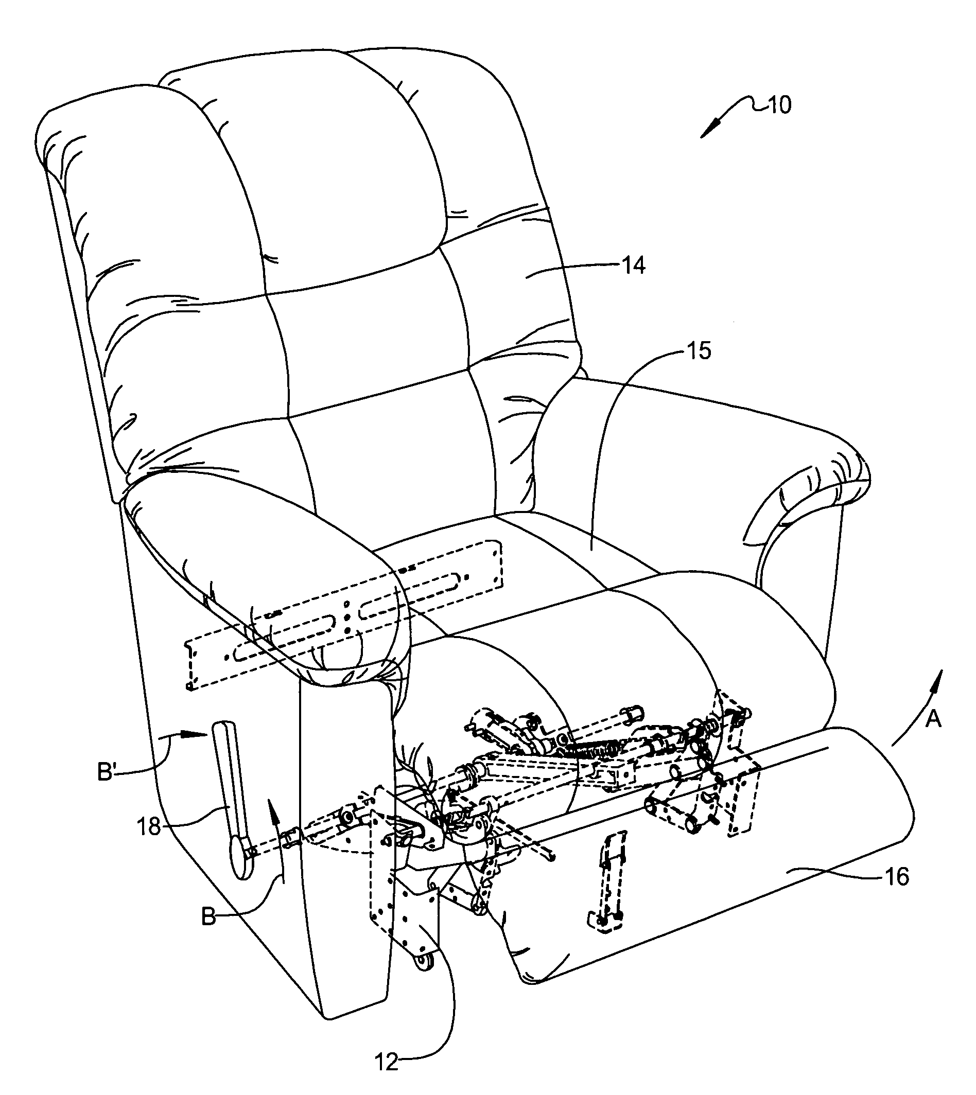
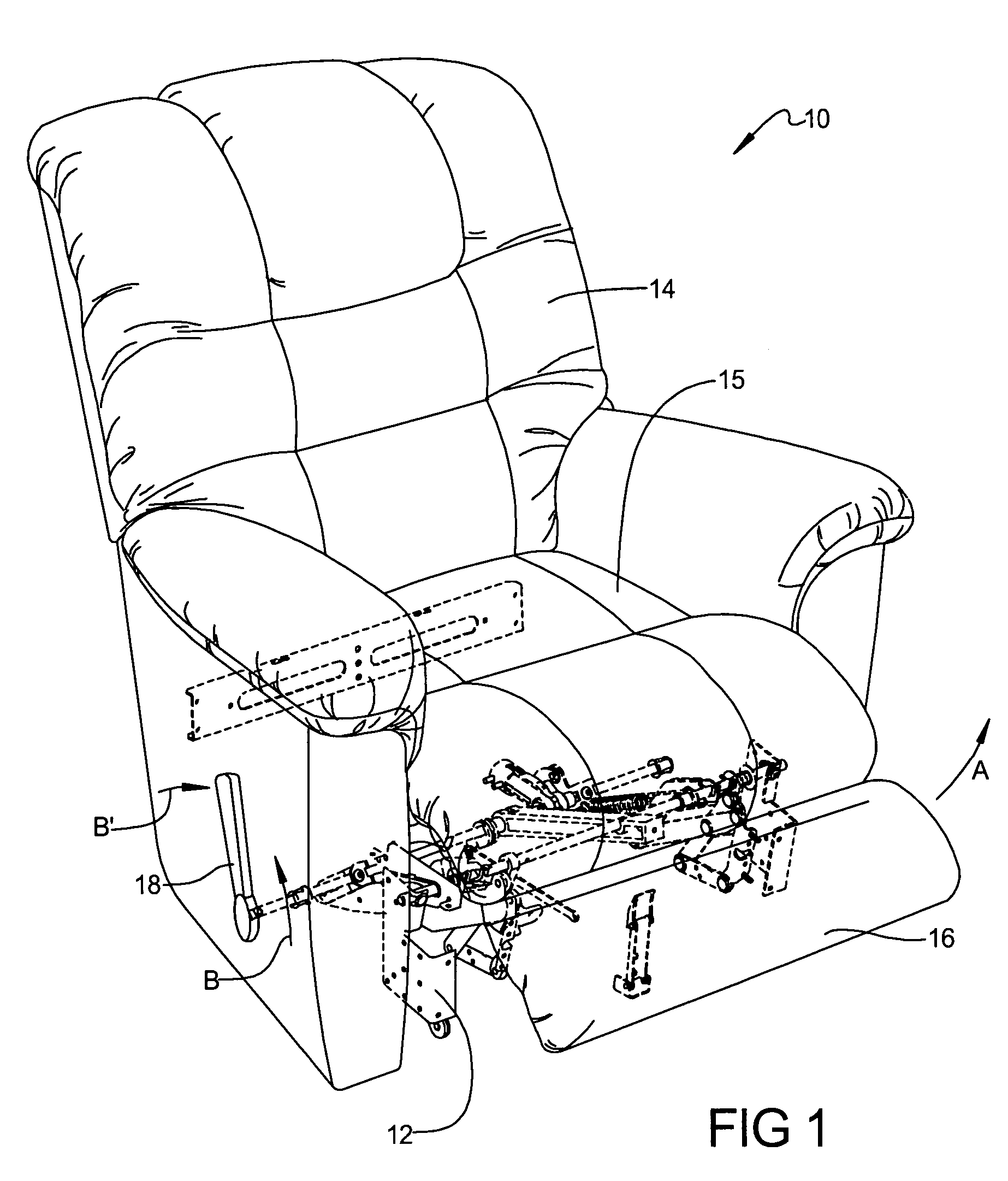
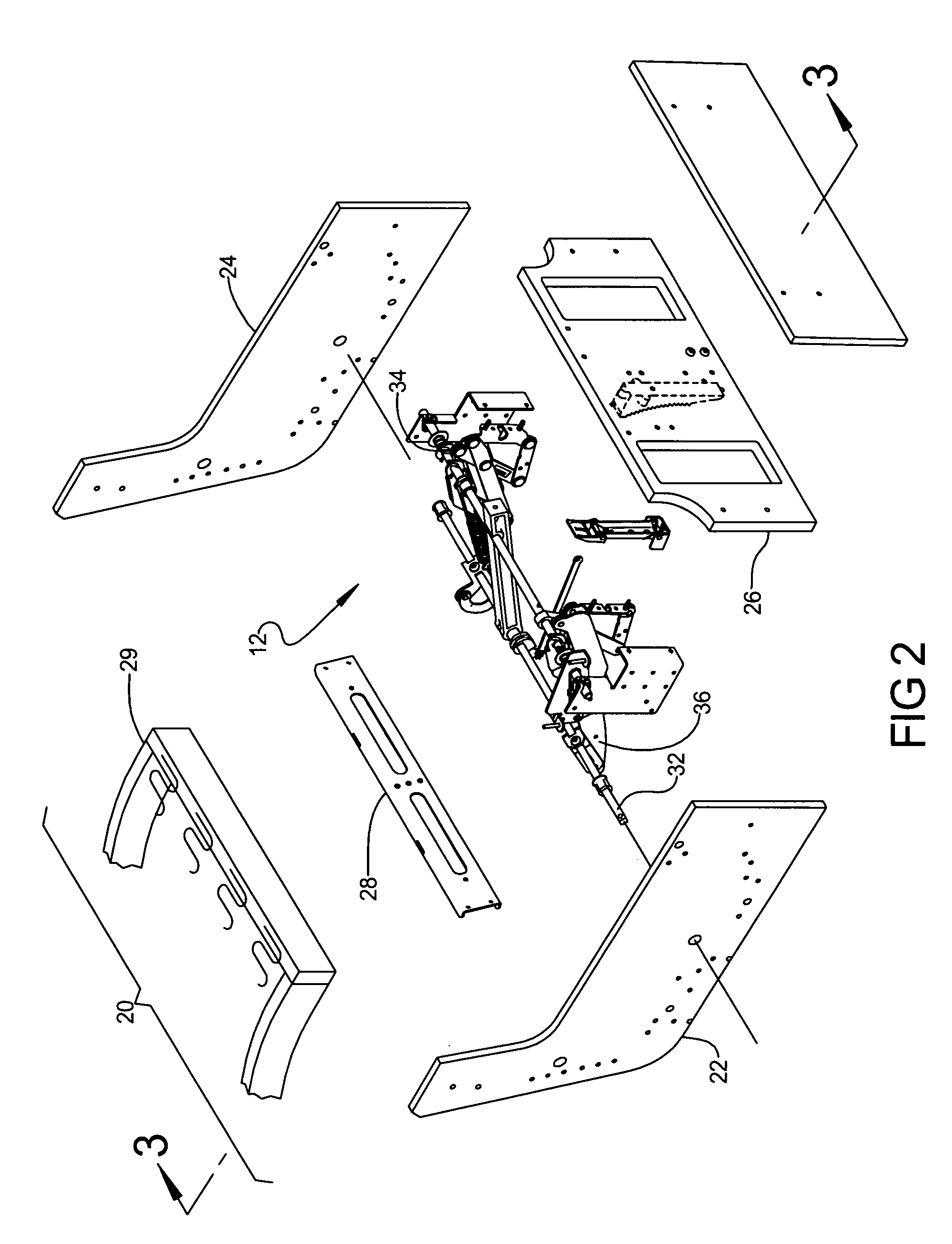
[0008]A multiple position leg rest mechanism of the present invention provides several advantages. By positioning a compressible material element between sector plates that control a leg rest assembly rotation position, a pin engages the compressible material element and limits the noise generated when locked positions of the mechanism are reached. The compressible material element also eliminates a need for lubricant which would be required if the pin and the sector plates are both made of metal. The sector plates can also be made of a polymeric material, further reducing the noise of the mechanism. Biasing elements ensure the pin continuously contacts the peripheral edge of the sector plates, which also therefore ensure the pin engages in recesses of the sector plates positioned to provide locked positions of a leg rest assembly.

Problems solved by technology

Due to the limited accessibility of the mechanism components after installation and during subsequent consumer use, continued application of the lubricant is difficult to ensure.
Increased mechanism noise and undue wear can therefore result.

Method used


Image

  • Multiple position leg rest mechanism
  • Multiple position leg rest mechanism
  • Multiple position leg rest mechanism

Examples


Embodiment Construction

[0023]The following description of several aspects of the invention is merely exemplary in nature and is in no way intended to limit the invention, its application, or uses.

[0024]In accordance with the teachings of the present invention, a multiple position leg rest mechanism for use in single and multi-person articles of furniture (i.e.: chairs, sofas and / or loveseats) is disclosed. A general understanding of the art to which the present invention pertains is disclosed in U.S. Pat. No. 3,325,210, Adjustable Leg Rest Locking Device, U.S. Pat. No. 5,570,927, Modular Wall Proximity Reclining Chair, and U.S. Pat. No. 6,655,732, Multiple Position Leg Rest Mechanism For A Reclining Chair, which are commonly owned by the assignee of the present invention and the disclosure of which is expressly incorporated by reference herein. As will be described, the pre-assembled actuation mechanism is uniquely suspended in a “fixed” pivot-point arrangement from pre-upholstered box-like frame componen...


PUM


Abstract

A three-position leg rest mechanism includes a link and sector members rotatably supported to the link. The sector members are coupled to a drive rod for rotation therewith. A biased pin engages the sector members and releasably locks with the sector members in each of three positions. A locking link end opposite the sector members is coupled to a support shaft of the actuation mechanism. An elastically compressible member is positioned between the sector members which is partially compressed by the pin as the pin moves relative to the sector members, reducing contact noise between the pin and the sector members.

Description

FIELD OF THE INVENTION[0001]The present invention relates in general to furniture members and more specifically to a device and method for operating a furniture member leg rest.BACKGROUND OF THE INVENTION[0002]Traditionally, furniture members such as reclining chairs are equipped with an actuation mechanism which is operatively interconnected between a prefabricated chair frame and a stationary base assembly. The actuation mechanism is typically a combination of various mechanical linkages operable for providing various comfort features such as independent reclining movement of a seat assembly as well as actuation of an extensible leg rest assembly and associated tilting of the chair frame.[0003]While many conventional reclining chairs operate satisfactorily, furniture manufacturers are continually striving to develop improved frames and actuation mechanisms for reducing system complexity and smoothness of operation as well as occupant comfort. Furthermore, there is a continuing des...

Claims


Application Information

Patent Timeline
Patent Type & Authority Patents(United States)
IPC IPC(8): A61G15/00A47C20/00A47C7/50
CPCA47C7/506A47C1/034
Inventor LAPOINTE, LARRY P
Owner LA-Z-BOY
Learn More