Downhole compressor

a compressor and downhole technology, applied in mechanical devices, non-positive displacement pumps, liquid fuel engines, etc., can solve the problems of reducing the flow velocity of the gas in the production tubing, affecting the operation of the compressor, so as to optimize the upward movement of the droplet, the effect of reliably functioning and inhibiting the condensation of vapor

Active Publication Date: 2008-03-04
CORAC ENERGY TECH
View PDF3 Cites 24 Cited by
  • Summary
  • Abstract
  • Description
  • Claims
  • Application Information

AI Technical Summary

Benefits of technology

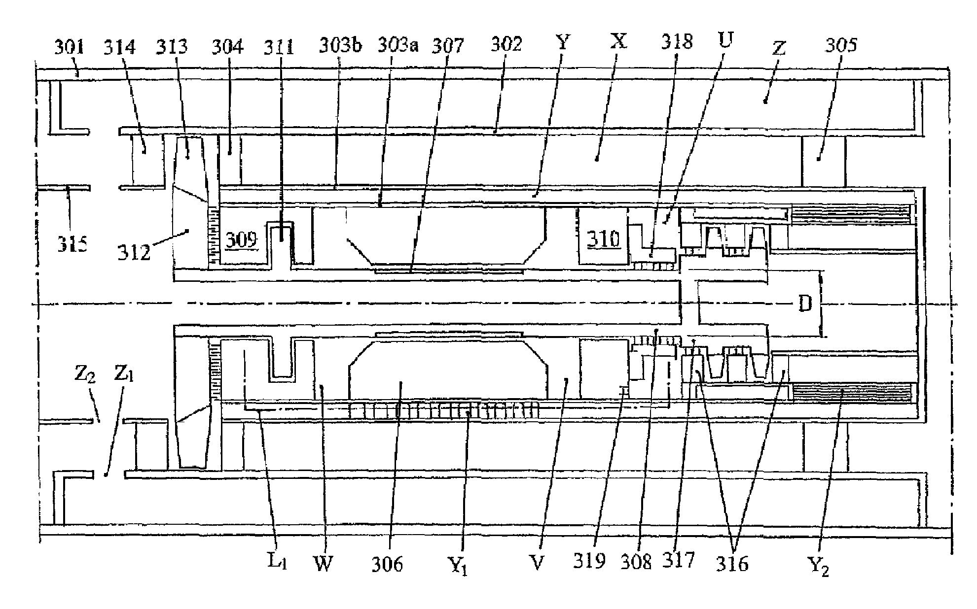
[0009]The present invention provides a rotary compressor which is suitable for use as a downhole compressor in that its gas bearings can be operated over very prolonged periods without requiring attention and in that its electric motor is adequately cooled by the produced gas.
[0012]The design of the motor rotor with an overhung compressor permits the rotor to be made hollow so that it can be better cooled.
[0016]It is envisaged that a purifier may be provided in the intake of the auxiliary compressor to remove particulates or other impurities suspended in the produced gas. The purifier may conveniently be an inertial separator.
[0017]In the preferred embodiment of the invention, the gas for the gas bearings flows in the opposite direction to the main axial gas flow of the produced gas. Though the gas can be discharged into the main flow of the produced gas after it has passed through the bearings, it is preferred to cool the gas by transferring heat from it to the main flow of produced gas, whereupon the gas can be recycled to the bearings by being returned to the intake of the auxiliary compressor. In this way, it is possible for the gas supplied to the gas bearings to flow essentially in a closed circuit.
[0018]When the gas supplied to the bearings flows in a closed circuit containing a purifier, the purifier does not have to be able to remove the particulate matter in all of the produced gas and it is therefore able to function reliably over prolonged periods of time. In this case the purifier may even be a simple filter.
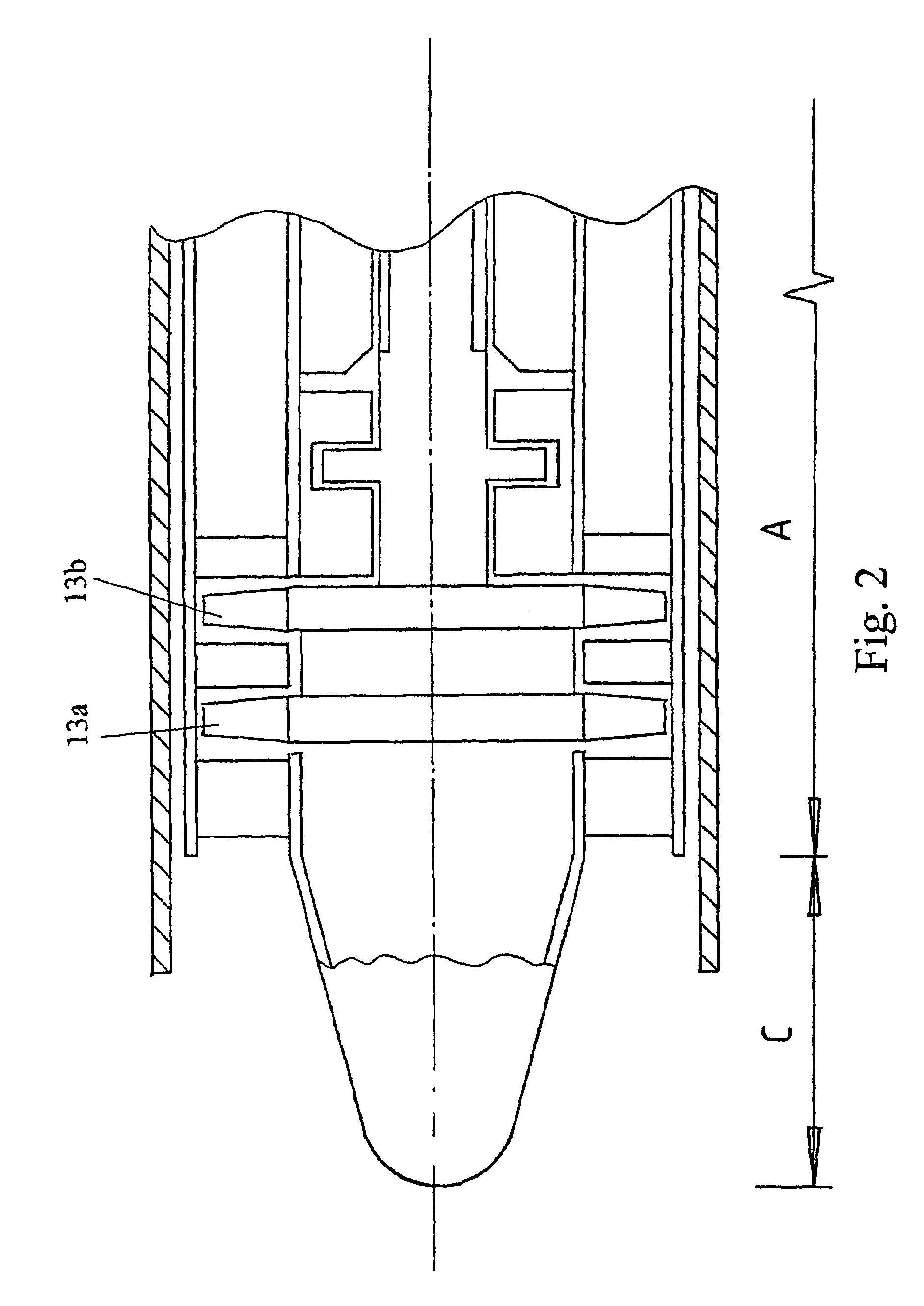
[0019]Because in the present invention gas always enters and leaves the compressor axially, it is possible to use a modular approach in which a number of such compressor modules are close coupled (aerodynamically and electrically) in tandem. Furthermore modules, and / or a set of modules in tandem, may be disposed at various depths in the production tube of a well in order to optimize the upward movement of droplets and inhibit the condensation of vapor.

Problems solved by technology

It is known in the art that the gas flowing from a well drilled into a gas reservoir frequently carries with it a burden of vapor and liquid droplets.
Consequently the flow velocity of the gas in the production tubing also falls, and eventually becomes too low to carry its burden of condensed liquids.
Gas production ceases to be economically effective before the gas flow ceases and operators will normally abandon a well long before the gas supply is exhausted.
Though the latter patent application discloses the concept of what is herein termed a downhole compressor, the compressor that it teaches has several limitations that would make it impracticable.
However, this presents problems with the maintenance of the reduction gearing which are not addressed in the application.
Furthermore, the application gives no details of how the gas bearings supporting the rotor shaft can be constructed or configured to receive an adequate supply of clean gas, nor does it resolve the rotor dynamic requirements of a shaft system supported on both gas and liquid lubricated bearings.

Method used


Image

  • Downhole compressor
  • Downhole compressor
  • Downhole compressor

Examples


Embodiment Construction

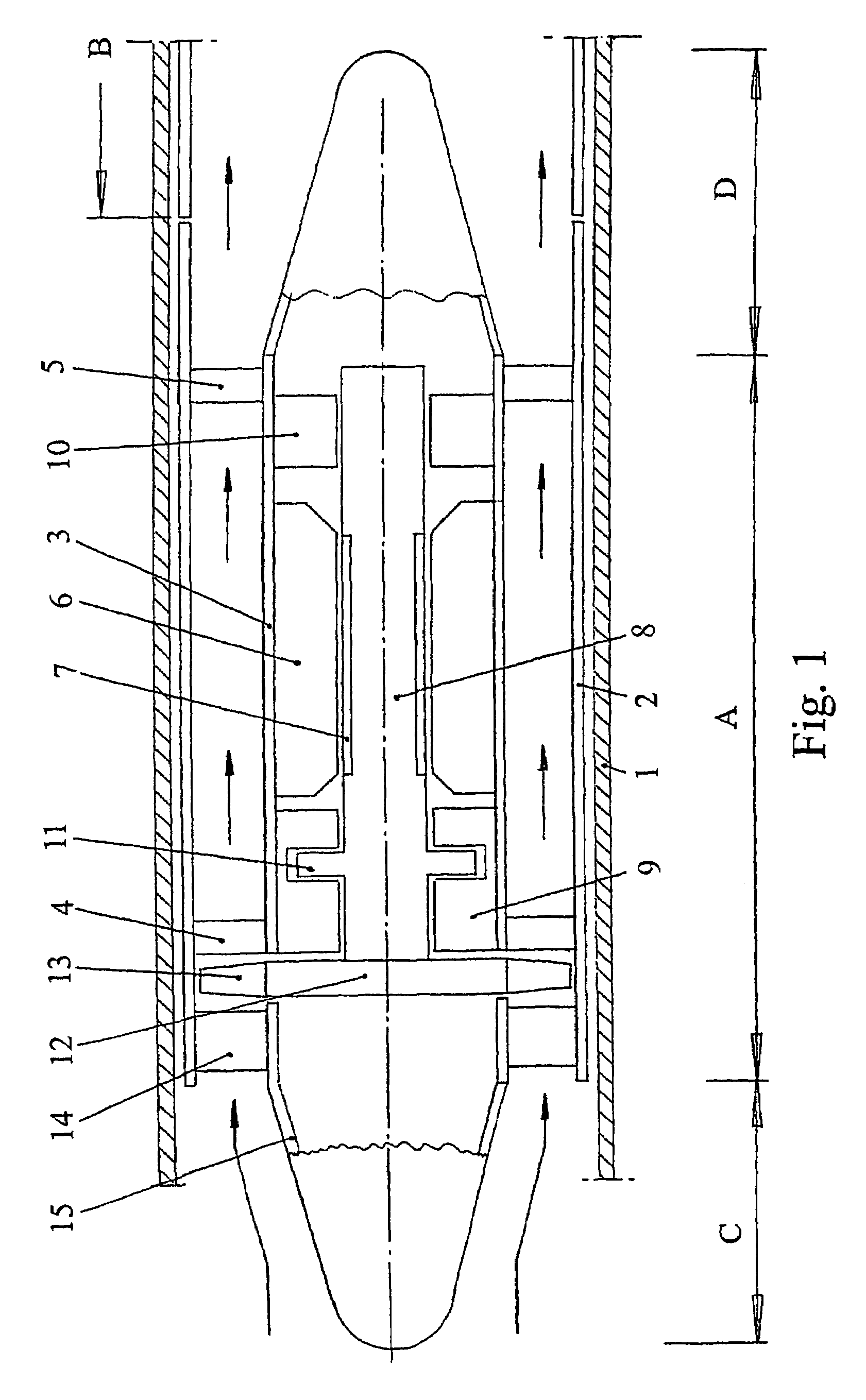
[0028]In FIG. 1, reference numeral 1 designates the production tube of a well, numeral 2 designates the outer shell of a compressor and numeral 3 refers to the casing of an electric motor. The casing of the motor is held concentrically within the shell of the compressor by the fixed blades 4 of the compressor and by the arms of a spider 5.

[0029]The motor is a high frequency induction motor and is supplied with high frequency current via an umbilical that is not shown in the Figure. Typically the speed of the motor is in the range of 20,000 rpm to 50,000 rpm. The preferred electric motor has a stator 6 and a permanent magnet armature or rotor 7 but it would be possible to use an alternative form of induction motor, such as a squirrel cage motor.

[0030]The rotor of the compressor, of which the armature of the motor forms a part, is designated 8. The rotor runs in journal bearings 9 and 10, and thrust is taken by a thrust bearing having a collar 11.

[0031]The motor drives the wheel 12 of...


PUM


Abstract

A downhole dynamic compressor comprises an electric motor having a stator 6 with stationary windings and an armature with permanent magnets 7 supported on gas bearings 9, 10 for rotation relative to the stator. The gas bearings 9 and 10 are arranged at the upstream and downstream opposite ends of the motor, respectively. The dynamic compressor has a bladed wheel 12 mounted on an overhanging end of the motor armature 7 that projects beyond the gas bearing 9 at the upstream end of the motor, whereby all the gas bearings of the compressor and the electric motor are arranged on the downstream side of the dynamic compressor.

Description

CROSS-REFERENCE TO RELATED APPLICATIONS[0001]This application is based upon and claims priority from PCT / GB03 / 00149, filed on Jan. 15, 2003, which is based on and claims priority from British Application 0200864.7 filed on Jan. 16, 2002, the entire disclosure of each of the aforementioned applications are each herein incorporated by reference in their entirety.BACKGROUND OF THE INVENTION[0002](1) Field of the Invention[0003]The present invention generally relates a downhole compressor, and more specifically to a compressor designed to be lowered into a well of a natural gas reservoir to assist in extracting gas from the reservoir.[0004](2) Description of Related Art[0005]It is known in the art that the gas flowing from a well drilled into a gas reservoir frequently carries with it a burden of vapor and liquid droplets. The pressure of gas at the base of a well falls as gas is extracted. Consequently the flow velocity of the gas in the production tubing also falls, and eventually bec...

Claims


Application Information

Patent Timeline
Patent Type & Authority Patents(United States)
IPC IPC(8): F04D25/02F04D5/00F04D25/06F04D29/04F04D29/057F04D29/58
CPCF04D25/06F04D29/057F04D29/584F04D29/5806F04D13/10
Inventor GOZDAWA, RICHARD JULIUS
Owner CORAC ENERGY TECH
Why Eureka
Try Eureka