
Flexible circuit to board connector

a flexible circuit and connector technology, applied in the field of devices, can solve the problems of limiting the serviceability of rigid pcbs, affecting the service life of rigid pcbs, and dislocating electrical contacts, so as to prevent lateral movement of the portion

Inactive Publication Date: 2008-03-04
SONY ERICSSON MOBILE COMM AB
View PDF17 Cites 11 Cited by
  • Summary
  • Abstract
  • Description
  • Claims
  • Application Information

AI Technical Summary

Benefits of technology

The solution provides a quick, easy, and cost-effective method for electrically interconnecting flexible circuits to PCBs, enhancing reliability and reducing the risk of connection failure under thermal or mechanical stress while allowing for easy disconnection during device repair or modification.

Problems solved by technology

Flexible circuits may be used as connectors in devices where flexibility, space savings, or production constraints limit the serviceability of rigid PCBs.
However, pressure may deform the securing arms of the electrical contacts of a ZIF connector, and / or may displace the electrical contacts.
When this happens, the ZIF connector may not provide reliable electrical connection between the flexible circuit and the PCB.
While BTB connectors may offer certain benefits, they are very unforgiving of tolerance, especially in the (XY) plane of a PCB.
The arrangement may be heated, causing the solder balls to melt.
Unfortunately, the solder balls in BGAs may not flex sufficiently, so that bending and thermal expansion of the PCB may be transmitted directly to the flexible circuit.
This may cause solder joints to fracture under high thermal or mechanical stress.
Another disadvantage of BGAs may be the difficulty in locating soldering faults once soldering is complete.
PGAs may be produced with more and more pins, and with decreasing spacing between the pins, which may cause difficulties for the soldering process.
As the pins get closer together, the danger of accidentally bridging adjacent pins with solder may grow.
Another significant disadvantage of LIF, ZIF, and BTB connectors, and BGA and PGA soldering is that such electrical interconnects may be expensive.
This may be a distinct disadvantage in today's world of high volume, low cost electrical devices.

Method used


Image

  • Flexible circuit to board connector
  • Flexible circuit to board connector
  • Flexible circuit to board connector

Examples


Embodiment Construction

[0044]The following detailed description of the invention refers to the accompanying drawings. The same reference numbers in different drawings may identify the same or similar elements. Also, the following detailed description does not limit the invention.

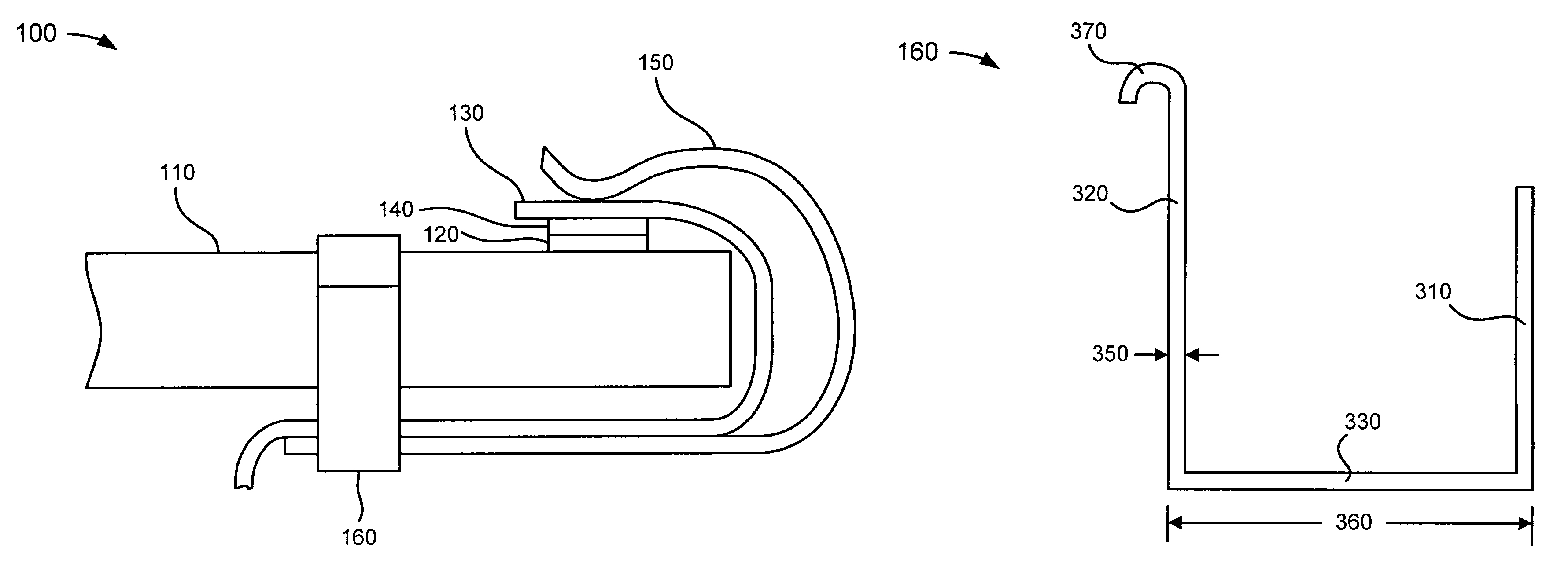
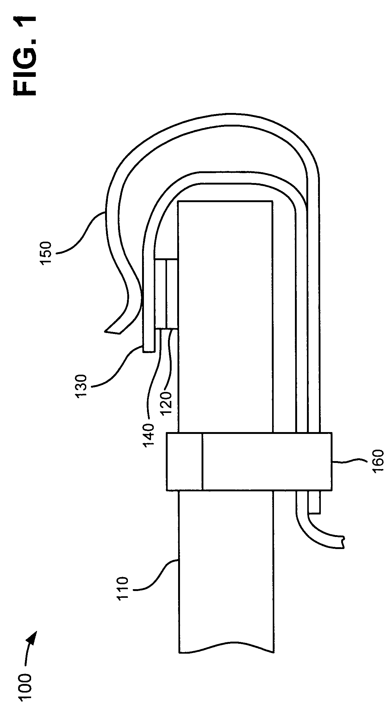
[0045]Implementations consistent with principles of the invention may relate to systems and methods for electrically interconnecting a flexible circuit to a PCB which may be provided in a device. The systems and methods may provide a quick, easy, and cost-effective way to electrically interconnect the flexible circuit to the PCB. In case of device repair and / or modification, the systems and methods may provide an easy way to disconnect the flexible circuit from the PCB.

[0046]The description to follow will describe a device. As used herein, a “device” may include a radiotelephone; a personal communications system (PCS) terminal that may combine a cellular radiotelephone with data processing, a facsimile, and data communications cap...


PUM


Abstract

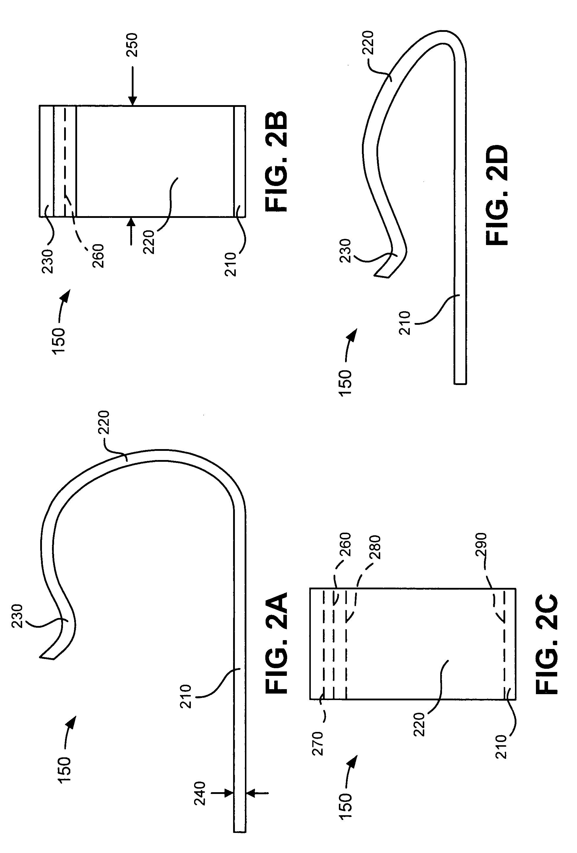
A system includes a rigid electrical device including a first contact, and a flexible electrical device including a second contact. The system further includes a spring clip connecting the first contact to the second contact to electrically interconnect the rigid electrical device to the flexible electrical device.

Description

BACKGROUND[0001]1. Field of the Invention[0002]Implementations described herein relate generally to devices and, more particularly, to a flexible circuit to board connector.[0003]2. Description of Related Art[0004]Printed circuit boards (PCBs) (which may be referred to as printing wiring boards (PWBs) or etched wiring board assemblies) may be used in computers, communications devices (e.g., pagers, personal digital assistants (PDAs), telephones, etc.), televisions, cameras, and / or many other devices. In a typical PCB, many electrical components may be attached to the top and / or bottom surfaces of the PCB. PCBs may be used to mechanically support and electrically connect the many electrical components using conductive pathways, or traces, which may be etched from copper sheets laminated onto a non-conductive substrate.[0005]Flexible circuits (which may be referred to as flexible printed circuits (FPCs)) may also be used in the devices described above in connection with PCBs. Flexible...

Claims


Application Information

Patent Timeline
Patent Type & Authority Patents(United States)
IPC IPC(8): H01R4/48H01R12/55H01R12/71
CPCH01R4/4881H01R12/714H01R12/79H05K3/365H01R4/4809H01R43/027H05K2201/10386H05K2201/2027H05K1/118H05K2201/056H05K2201/10265H01R4/4821H01R13/05
Inventor SIMONSSON, OLOF SIMONKAZEMIFAR, OMIDHALL, MIKAEL PAR-OSKARKARLSSON, MAIKO ANNELIPETERSSON, HAKAN KLAS
Owner SONY ERICSSON MOBILE COMM AB
Learn More