Method and apparatus for performing CW doppler ultrasound utilizing a 2D matrix array

a technology of matrix array and doppler ultrasound, which is applied in the field of continuous wave (cw) doppler ultrasound methods and apparatuses utilizing a two-dimensional (2d) matrix array, can solve the problems of introducing errors in the cw signal processing chain, the dynamic range of the preamplifiers received in the probe,

Active Publication Date: 2008-03-04
GENERAL ELECTRIC CO
View PDF13 Cites 78 Cited by
  • Summary
  • Abstract
  • Description
  • Claims
  • Application Information

AI Technical Summary

Problems solved by technology

The receive preamplifiers in the probe have a limited dynamic range.
Driving the preamplifiers into saturation introduces errors in the CW signal processing chain.

Method used


Image

  • Method and apparatus for performing CW doppler ultrasound utilizing a 2D matrix array
  • Method and apparatus for performing CW doppler ultrasound utilizing a 2D matrix array
  • Method and apparatus for performing CW doppler ultrasound utilizing a 2D matrix array

Examples


Embodiment Construction

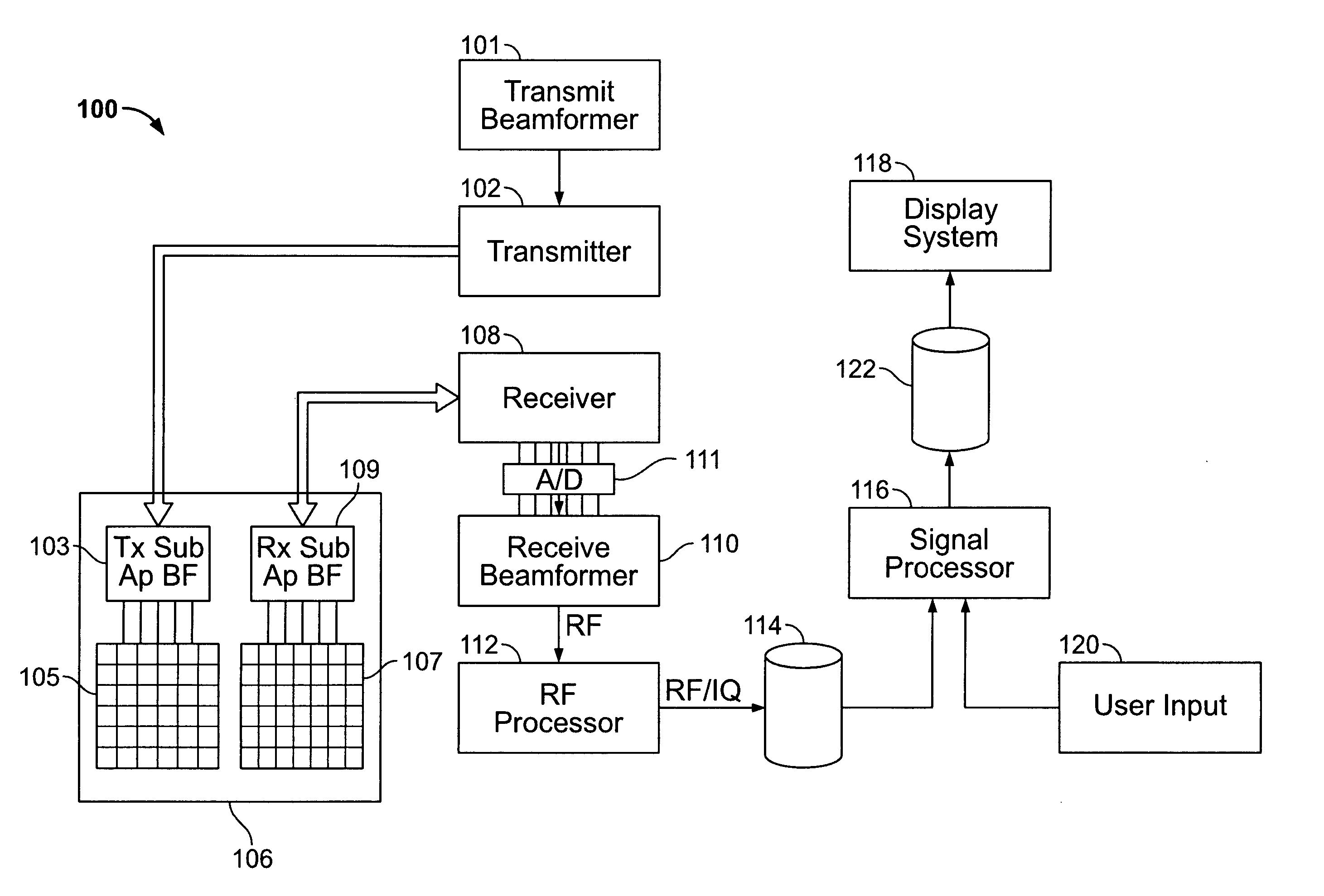
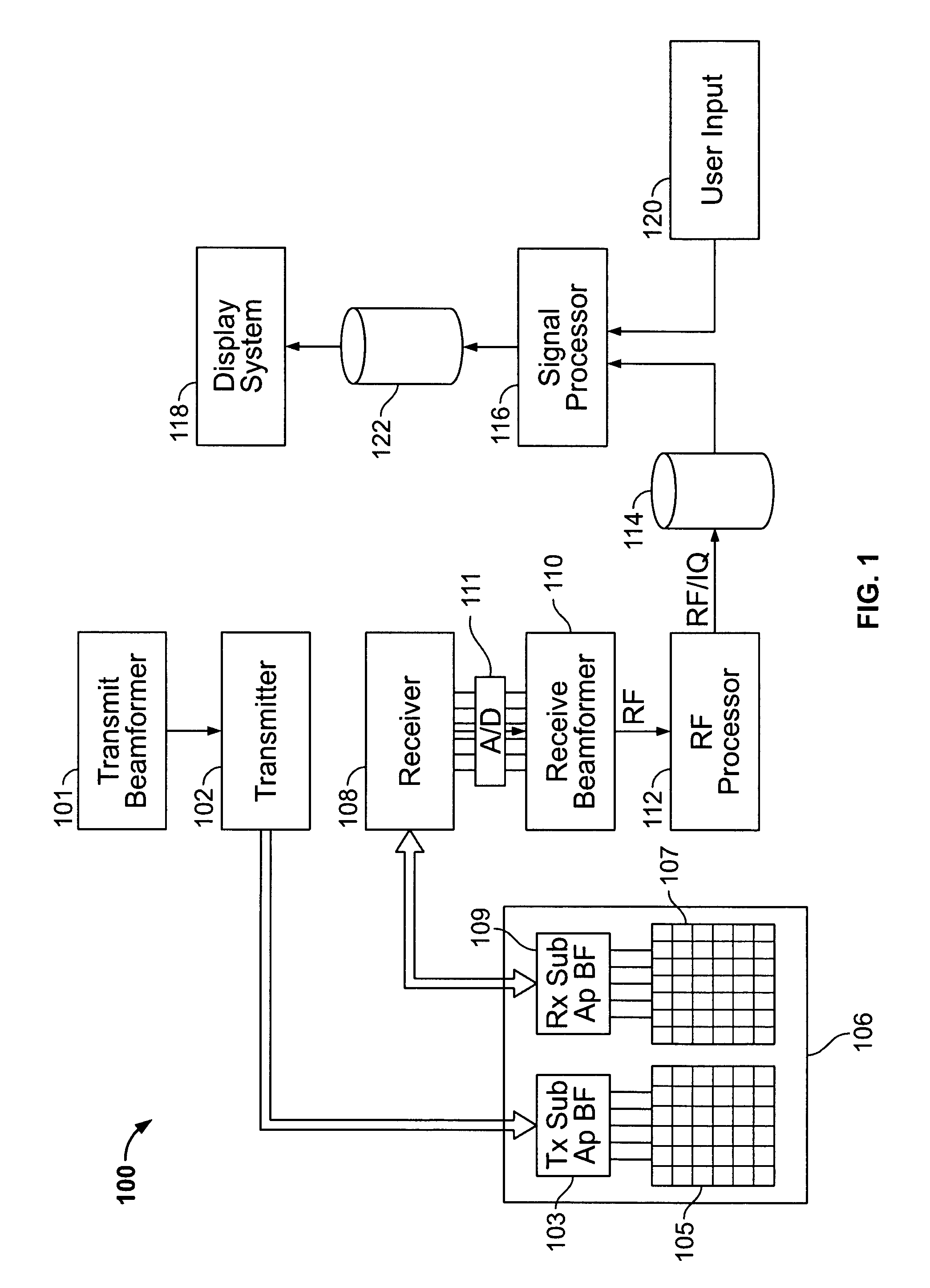
[0015]FIG. 1 illustrates a block diagram of an ultrasound system 100 formed in accordance with an embodiment of the present invention. The ultrasound system 100 includes a transmitter 102 which drives a probe 106. The probe 106 may include a 1D array, a 1.25 D array, a 1.5 D array, a 1.75 D array, a 2 D array and the like. Optionally, the probe could stand-alone CW probe with a single transmit element and a single receive element. In FIG. 1, a two dimensional (2D) array of elements 104 is shown within the probe 106. The probe 106 includes a transmit group of elements 105 and a receive group of elements 107. A transmit beamformer 101 controls a transmitter 102 which, through transmit sub-aperture beamformers 103, drives a group of elements 105 to emit continuous wave (CW) ultrasonic transmit signals into a region of interest (e.g., human, animal, underground cavity, physical structure and the like). The transmitted CW ultrasonic signals are back-scattered from structures in the objec...


PUM


Abstract

An ultrasound system is provided comprising an ultrasound probe having a 2D matrix of transducer elements transmitting a continuous wave (CW) Doppler transmit signal into an object of interest. The CW transmit signal includes a dither signal component and the probe receives ultrasound echo signals from the object in response to the CW transmit signal. The probe generates an analog CW receive signal based on the ultrasound echo signals. An analog to digital (A / D) converter converts the analog CW receive signal to a digital CW receive signal at a predetermined sampling frequency and a processor processes the digital CW receive signal in connection with CW Doppler imaging.

Description

BACKGROUND OF THE INVENTION[0001]The present invention generally relates to continuous wave (CW) Doppler ultrasound methods and apparatus utilizing a two-dimensional (2D) matrix array, and more particularly to CW Doppler methods and apparatus that utilize a dither signal component in the CW transmit signal.[0002]Ultrasound systems have been proposed that afford a variety of techniques for examining an object of interest, whether it be human, animal, underground cavities, physical structures and the like. Examples of medical diagnostic imaging techniques include B-mode imaging, color flow imaging, power Doppler imaging, pulse-wave Doppler imaging, tissue velocity imaging, continuous wave Doppler imaging and the like. The various imaging techniques may include presenting to the user 2D or 3D images, temporal graphs (e.g., motion over time), and the like. During CW Doppler imaging, conventional systems drive an ultrasound probe to transmit a non-interrupted continuous wave ultrasound s...

Claims


Application Information

Patent Timeline
Patent Type & Authority Patents(United States)
IPC IPC(8): A61B8/00A61B8/02A61B8/12A61B8/14
CPCG01S7/5203G01S15/8925G01S15/8927G01S15/8959
Inventor KRISTOFFERSEN, KJELLLIE, GLENN REIDAR
Owner GENERAL ELECTRIC CO
Why Eureka
Try Eureka