Method and apparatus for cementing a screw anchor

a screw anchor and screw technology, applied in the surgical field, can solve the problems of current fastening devices failing and the fastener becoming dislodged from the bon

Inactive Publication Date: 2008-03-04
BIOMET MFG CORP
View PDF95 Cites 73 Cited by
  • Summary
  • Abstract
  • Description
  • Claims
  • Application Information

AI Technical Summary

Benefits of technology

[0005]The present invention provides for a bone screw anchor that is capable of securely fastening a fixation device to bone that is weak or brittle. The fastening device includes a distal region that may terminate in an open aperture or a solid tapered terminus. The distal region may include a plurality of cutting flutes and an elongated helical thread extending through an intermediate region, so as to provide a self cutting anchor. The proximal region has a receptor for receiving a driver so as to aid in the driving of the anchor directly within the bone or within a pre-drilled, elongated bore within the bone.

Problems solved by technology

While current fastening devices are capable of securing fixation devices to bone that is strong and healthy, current fastening devices fail when the bone is weak and brittle, as is often found in the elderly.
Weak and brittle bone severely hampers fastener purchase and often results in the fastener becoming dislodged from the bone.

Method used


Image

  • Method and apparatus for cementing a screw anchor
  • Method and apparatus for cementing a screw anchor
  • Method and apparatus for cementing a screw anchor

Examples


first embodiment

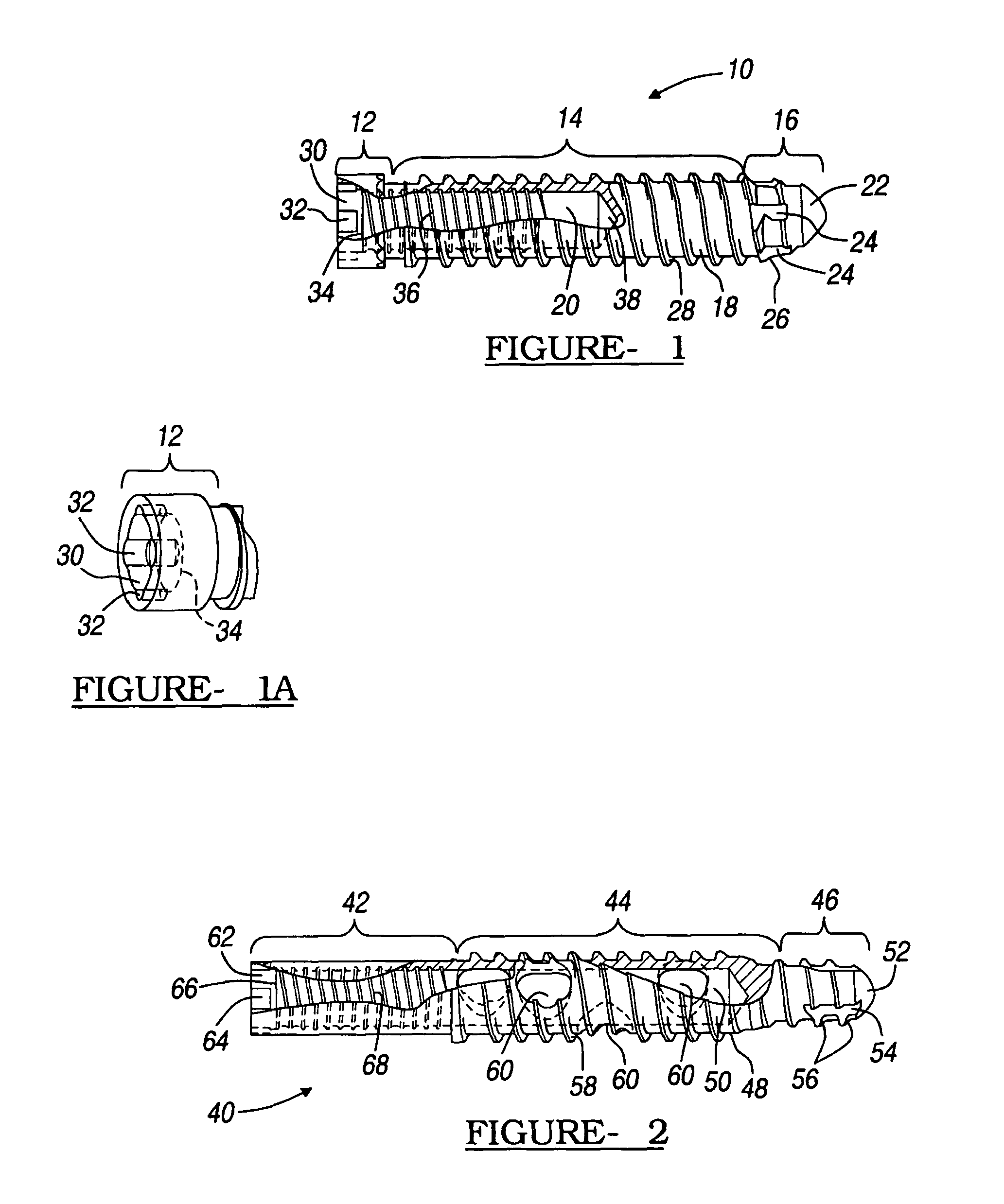
[0037]Like anchor 10 of the first embodiment, anchor 40 may be manufactured using any suitable biocompatible material such as, but not limited to, stainless steel, polyethylene, titanium, and cobalt chrome molybdenum. Regardless of the material used, it is preferred that the material be sufficiently rigid to allow the anchor to be self-cutting and should be compatible with the particular device secured using anchor 40, however, this may not be necessary in all applications. Preferably, anchor 40 and the secured device are of the same material.

[0038]Also similar to anchor 10, the configuration and composition of anchor 40 allows it to cut and rigidly engage a variety of different bones and bone regions. For example, anchor 40 is suitable for penetrating and securely engaging both cortical and cancellous regions of the femur bone or any other appropriate bone.

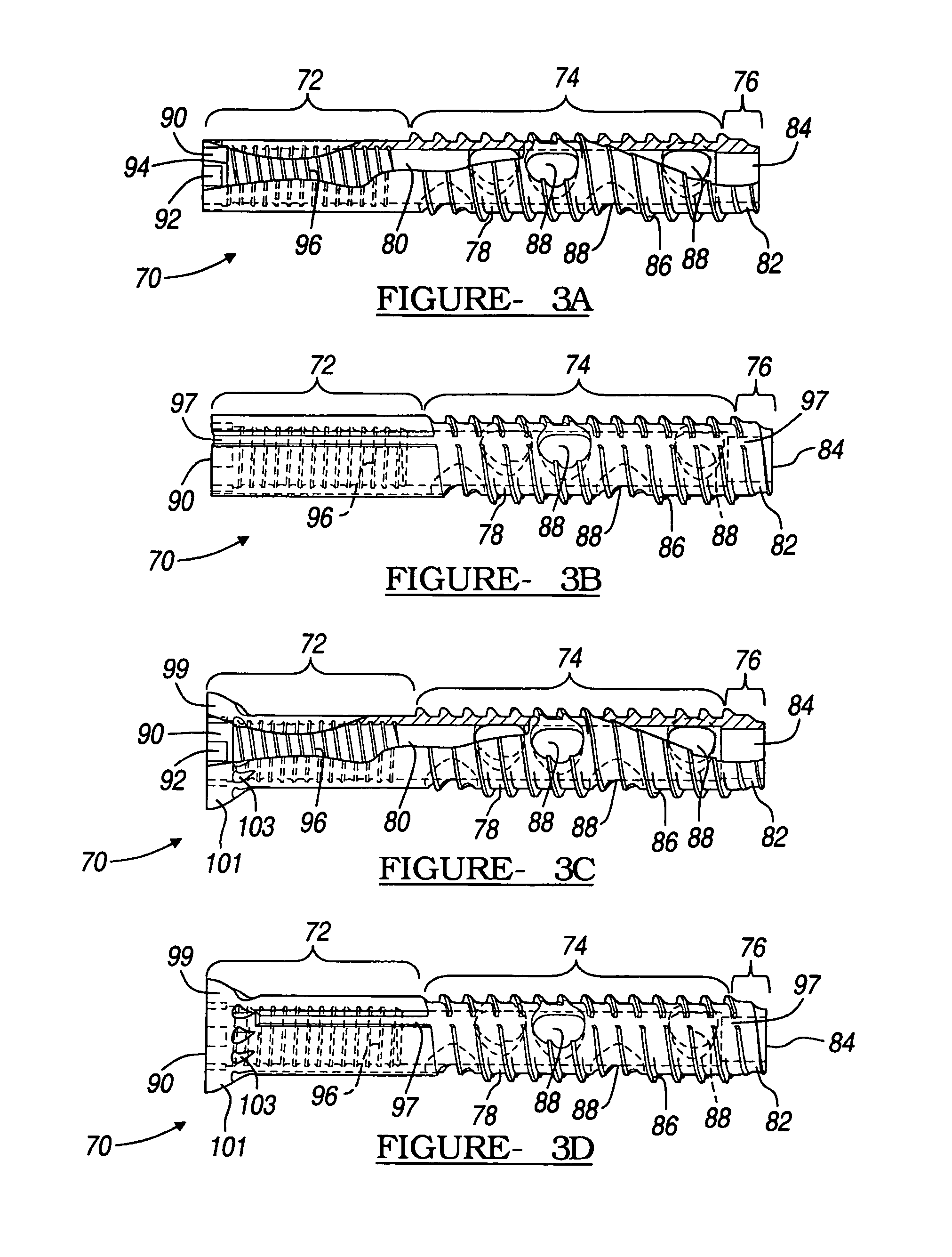
[0039]A screw anchor according to a third preferred embodiment of the present invention is illustrated at FIG. 3A at reference ...

second embodiment

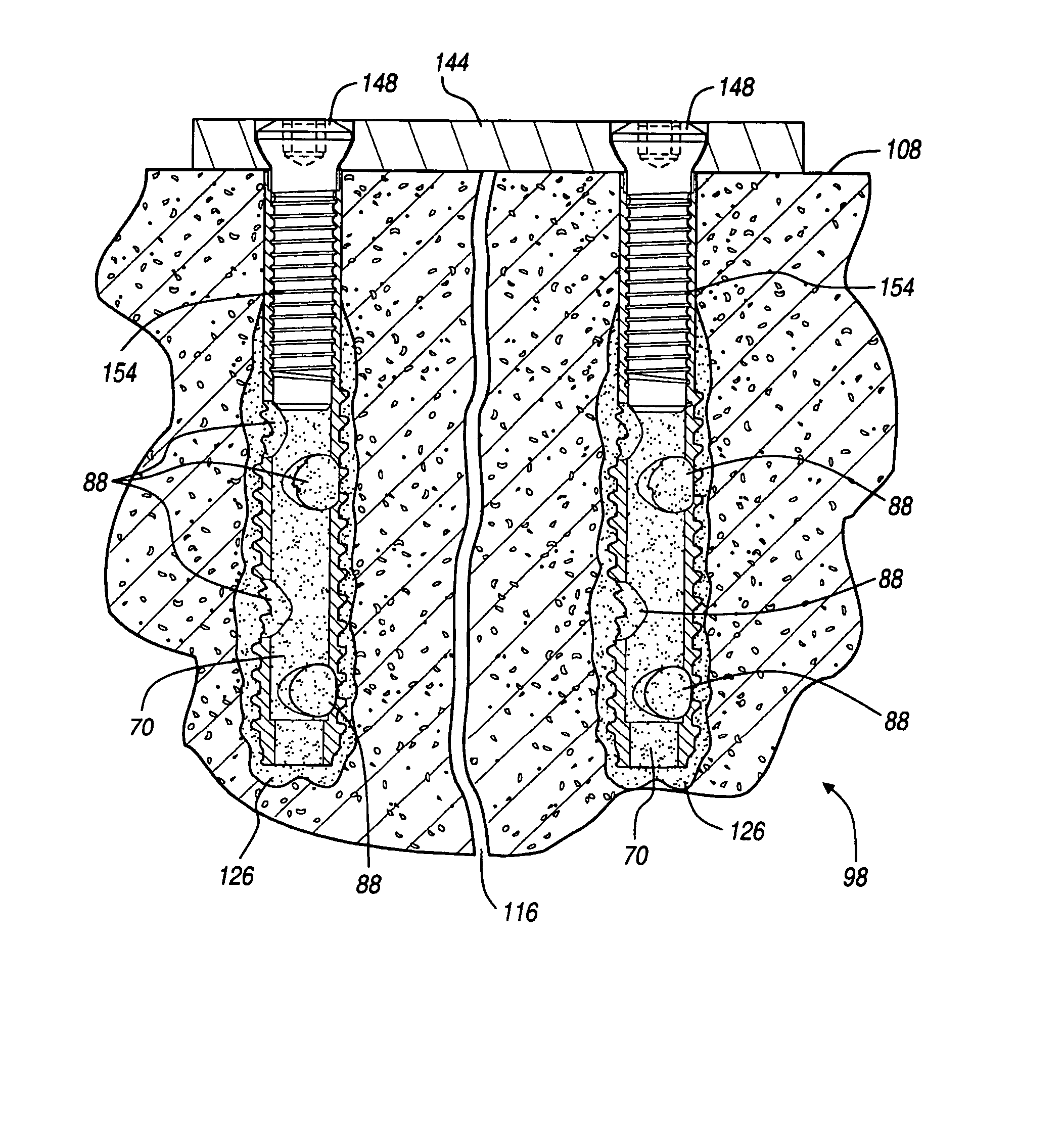
[0042]Similar to anchor 40 of the second embodiment, the intermediate region 74 of anchor 70 contains a plurality of ports 88. The ports 88 may be placed at any location within the intermediate region 74 but are preferably placed in a staggered configuration at 120° intervals throughout the intermediate region 74, as seen in FIG. 3. The ports 88 extend from the exterior surface 78 to the interior bore 80 and allow for the passage of material, such as bone cement, from the interior bore 80 to the exterior surface 78. The presence of ports 88 interrupts helical thread 86.

[0043]Formed within the proximal region 72 is a receptor 90. The receptor 90 has at least one niche or groove 92 for receiving a corresponding projection of a suitable driving tool. The receptor 90 takes the place of a head and allows the anchor 70 to be driven completely within the bone so that no portion of the anchor 70 extends from the bone. The receptor 90 contains an opening 94 to provide access to the interior ...


PUM


Abstract

A bone screw anchor capable of securely fastening a fixation device to weak or brittle bone. The anchor includes a distal region terminating in an open aperture or a solid tapered terminus. The distal region may include cutting flutes and a helical thread extending through an intermediate region, so as to make the anchor self-cutting. The proximal region has a receptor for receiving a driver for driving the anchor within a bore or hole within the bone. The anchor has an interior bore with internal threads for receiving a bone screw used to secure a fixation device to the anchor. The bore may have a plurality of ports providing passage to the exterior of the anchor. Once seated entirely within the receptor, the anchor's position is secured using bone cement. Bone cement is delivered to the bore or hole before the anchor is placed in the receptor or after via the ports.

Description

CROSS-REFERENCE TO RELATED APPLICATIONS[0001]This application claims the benefit of U.S. Provisional Application No. 60 / 392,492, filed on Jun. 28, 2002. The disclosure of the above application is incorporated herein by reference.FIELD OF THE INVENTION[0002]The present invention relates to surgical applications for the repair of bone fractures and deformities. More particularly, the present invention relates to a method and apparatus for anchoring a bone fixation device to an exterior bone surface.BACKGROUND OF THE INVENTION[0003]It is well known in the art to use fixation devices to aid in the repair of bone defects such as bone fractures. Fixation devices are available in a wide variety of different shapes and sizes, such as a rigid plate. After the defective bone is set in proper position by a physician, the fixation device is used to secure the bone in this position during the healing process. Preferably, the fixation device is placed over the defective portion of the bone and an...

Claims


Application Information

Patent Timeline
Patent Type & Authority Patents(United States)
IPC IPC(8): A61B17/56
CPCA61B17/686A61B17/7098A61B17/80A61B17/864
Inventor VANDEWALLE, MARK V
Owner BIOMET MFG CORP
Why Eureka
Try Eureka