Standing wave particle beam accelerator

a beam accelerator and wave particle technology, applied in accelerators, klystrons, electric discharge tubes, etc., can solve the problems of difficult and costly implementation of accelerators limited to 2 to 3 modalities, and achieve the effects of reducing separation between resonant modes, increasing interactions between adjacent modes, and a broader bandwidth for accelerators

Active Publication Date: 2008-03-04
HONEYWELL INT INC +1
View PDF15 Cites 47 Cited by
  • Summary
  • Abstract
  • Description
  • Claims
  • Application Information

AI Technical Summary

Benefits of technology

[0007]In accordance with some embodiments, an accelerator for accelerating a particle beam is provided. The accelerator includes a main body having a plurality of electromagnetic cavities coupled in series, and a first coupling body having a first side cavity coupled to one of the electromagnetic cavities through a first opening, and to another of the electromagnetic cavities through a second opening, wherein the first opening and the second opening have different configurations. The accelerator further includes a pair of conductive capacitively coupled noses secured to side walls of the first coupling body, wherein the pair of noses have equal lengths. By configuring the first and the second openings to be different, separations between resonant modes are reduced. However, such configuration also allows an energy switch to operate in a wider range of energy levels without significantly increasing interactions between adjacent modes. This in turn provides a broader bandwidth for the accelerator when an energy switch is in use, allowing the accelerator to generate x-ray beams with a broader range of energy levels and minimum energy spread.
[0009]In accordance with some embodiments, a field step control is provided. The field step control includes a coupling body having a first end, a second end, a cavity extending between the first and the second ends, and a pair of conductive capacitively coupled noses secured to side walls of the coupling body, the pair of noses having equal lengths, wherein the first end is sealed, the second end is secured to a wall having a first opening and a second opening, and the first opening has a cross sectional dimension that is different from a cross sectional dimension of the second opening. The field step control allows an accelerator to achieve a balance between optimized operational stability and optimized operational range. This in turn allows the accelerator to generate x-ray beams with a wider range of energy levels and minimum energy spread.

Problems solved by technology

From a manufacturing perspective, accelerators limited to 2 to 3 modalities are difficult and costly to implement.

Method used


Image

  • Standing wave particle beam accelerator
  • Standing wave particle beam accelerator
  • Standing wave particle beam accelerator

Examples


Embodiment Construction

[0022]Various embodiments of the present invention are described hereinafter with reference to the figures. It should be noted that the figures are not drawn to scale and that elements of similar structures or functions are represented by like reference numerals throughout the figures. It should also be noted that the figures are only intended to facilitate the description of specific embodiments of the invention. They are not intended as an exhaustive description of the invention or as a limitation on the scope of the invention. In addition, an illustrated embodiment needs not have all the aspects or advantages of the invention shown. An aspect or an advantage described in conjunction with a particular embodiment of the present invention is not necessarily limited to that embodiment and can be practiced in any other embodiments of the present invention even if not so illustrated.

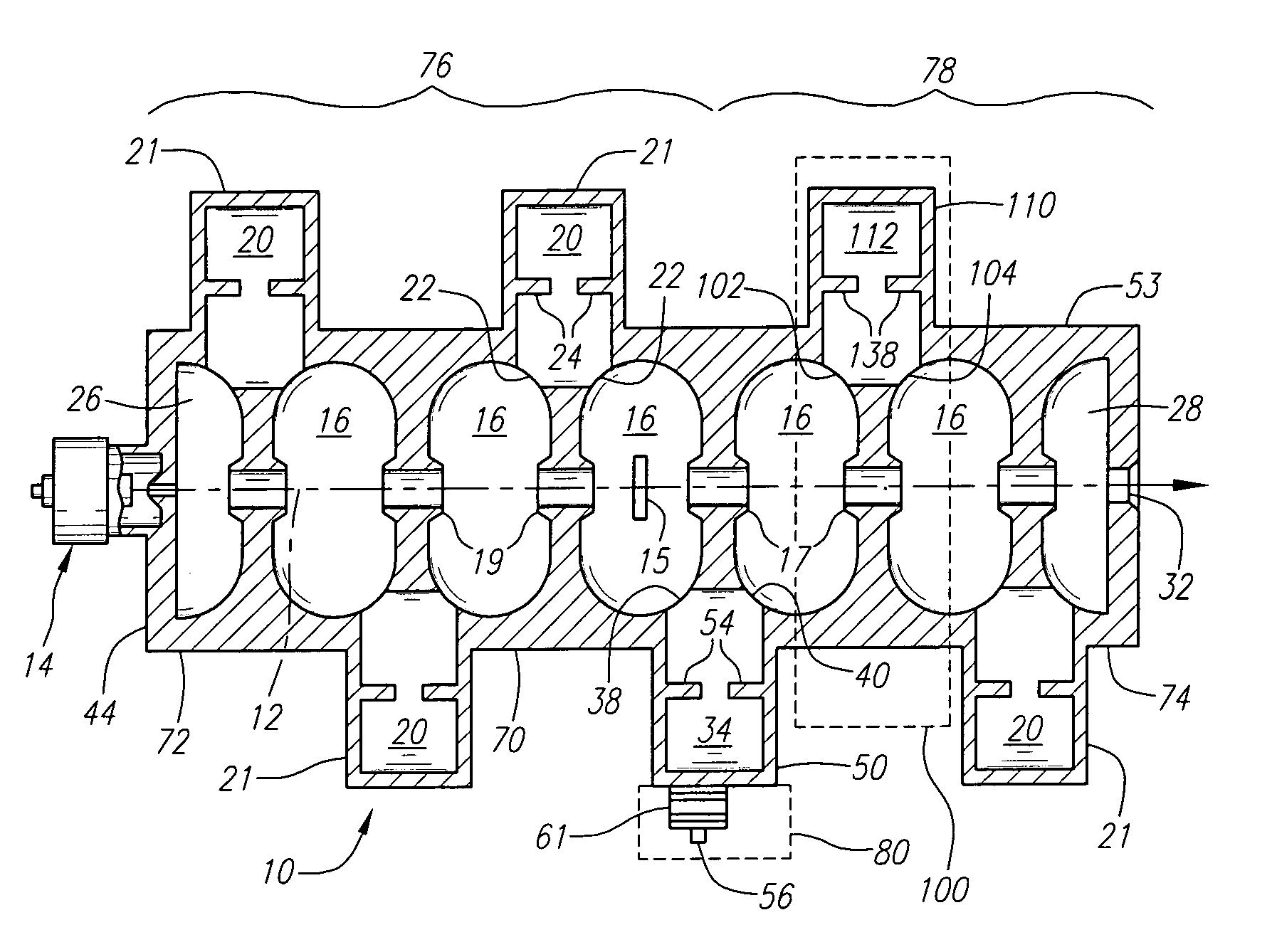
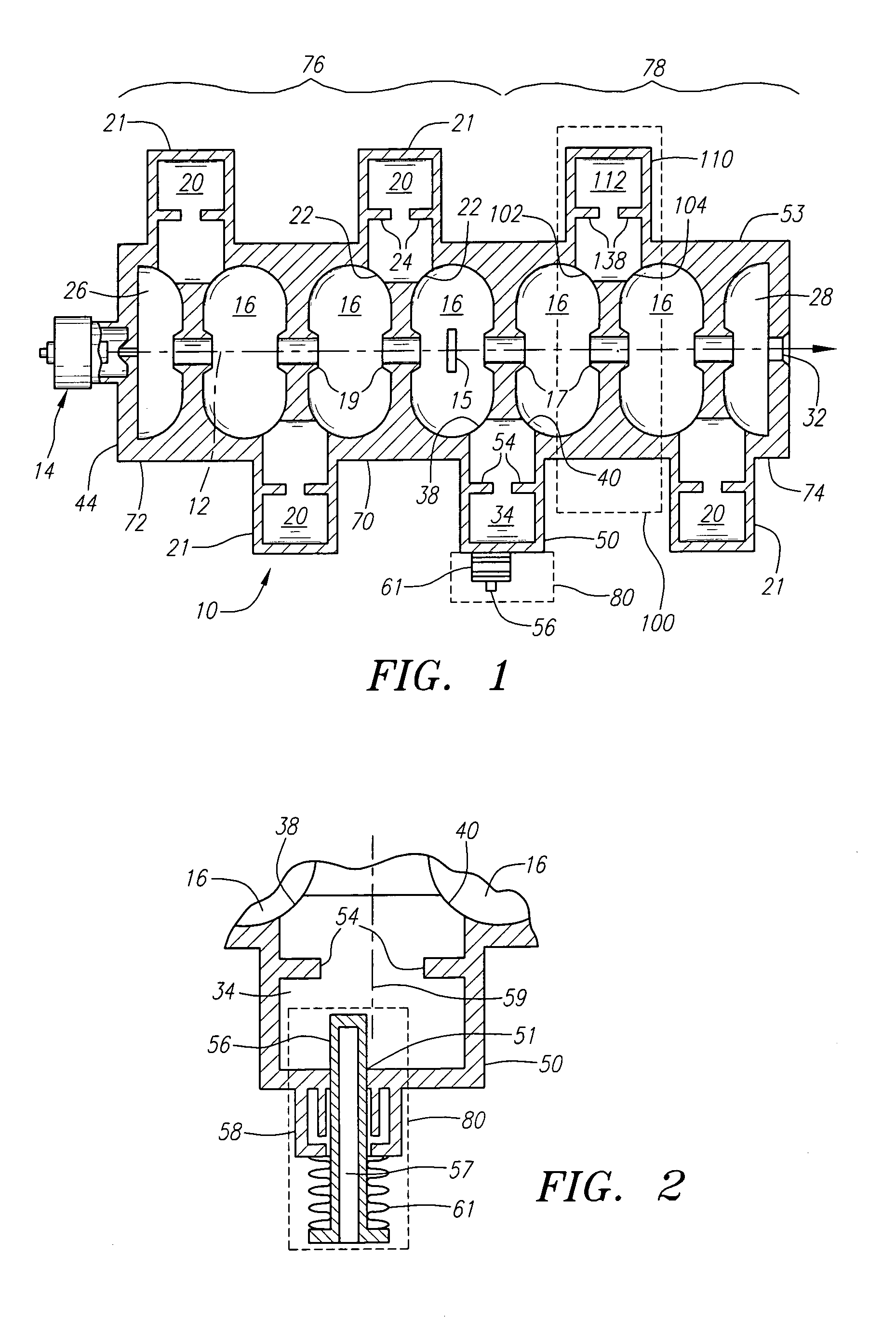
[0023]FIG. 1 is a schematic axial sectional view of a charged particle standing wave accelerator 10 embo...


PUM


Abstract

An accelerator for accelerating a particle beam includes a main body having a plurality of electromagnetic cavities coupled in series, and a first coupling body having a first side cavity coupled to one of the electromagnetic cavities through a first opening, and to another of the electromagnetic cavities through a second opening, wherein the first opening and the second opening have different configurations. The accelerator further includes a pair of conductive capacitively coupled noses secured to side walls of the first coupling body, wherein the pair of noses have equal lengths.

Description

BACKGROUND OF THE INVENTION[0001]1. Field of the Invention[0002]This invention relates generally to standing wave particle beam accelerators, and more particularly, to electron accelerators for generating x-ray and electron beams of different energies.[0003]2. Background of the Invention[0004]Standing wave particle beam accelerators have found wide usage in medical accelerators where the high energy particle beam is employed to generate x-rays. In this application, the beam energy and output dose-rate must be stable. It is also desirable that the energy of the particle beam be switchable readily and reliably to provide treatment beams of different energies to enable a range of dose-depth penetration during medical treatments.[0005]Various techniques for controlling the beam energy have been employed. In U.S. Pat. No. 4,286,192 to Tanabe and Vaguine, the energy is controlled by reversing the accelerating fields in one part of the accelerator to decelerate the beam. In U.S. Pat. No. 4...

Claims


Application Information

Patent Timeline
Patent Type & Authority Patents(United States)
IPC IPC(8): H01J25/10H05H9/04
CPCH05H9/048H05H9/044
Inventor MEDDAUGH, GARD E.TRAIL, MARK E.WHITTUM, DAVID
Owner HONEYWELL INT INC
Why Eureka
Try Eureka