Tracheostomy system

a tracheostomy and tracheostomy technology, applied in the field of new tracheostomy tube and tracheostomy system, can solve the problems of difficulty in inserting a larger tube, difficulty in removing a smaller tracheostomy tube and attempting to place a larger tube, and difficulty in achieving the necessary opening for placing a tracheostomy tube,

Inactive Publication Date: 2008-03-11
NBS ACQUISITION
View PDF22 Cites 36 Cited by
  • Summary
  • Abstract
  • Description
  • Claims
  • Application Information

AI Technical Summary

Benefits of technology

[0010]The tracheostomy system of various embodiments of this invention includes a needle and wire guide assembly insertable percutaneously into the lumen of the trachea and a dilator including a flexible tubular body terminating at its distal end in a tapered tip portion attached to the wire guide assembly. A radially expandable or contractible outer tracheostomy tube having a tubular passageway therein is mounted about the dilator for insertion into the lumen of the trachea of the patient. Upon removal of the dilator from the radially expandable / contractible outer tracheostomy tube, a cannula of desired tubular cross-section is inserted through the tracheostomy tube. In accordance with the embodiments of this invention, a plurality of dilators of various diameters are utilized for insertion into the radially-expandable / contractible outer tracheostomy tube to radially expand the tracheostomy tube to a desired diameter to prepare the tube to receive a cannula of a certain diameter, with the outer tube automatically assuming or adjusting to a larger or smaller size depending upon the diameter of the dilator inserted whereby various sized cannulas can be inserted without having to remove the outer tracheostomy tube.

Problems solved by technology

But, if a patient's clinical course worsens, it is sometimes difficult to insert the larger tube.
This is because the ostomy site or tracheostoma usually closes very quickly as the soft tissue heals around the smaller tracheostomy tube, making it difficult and sometimes dangerous to remove a smaller tracheostomy tube and attempt to place a larger tube in its place.
U.S. Pat. No. 6,706,017 recognized that the use of numerous dilators in order to achieve the necessary opening for placing a tracheostomy tube is problematic.
The '017 patent describes such a system as time-consuming and includes the possibility of creating tissue lesions and a false passage.
Further, as described in the '017 patent, once the largest of the series of dilators is placed, the introduction of the trachea tube is often difficult because there is no protection for the tracheostomy cuff during its introduction, and this sometimes results in a rupture of the cuff.
Further, such dilators are also not adapted for all the available tracheostomy tube.
It does not alleviate in any way the need for frequent tube changes or the complications thereof.
In addition, a one step tube insertion is not possible because the device described in the '017 patent is merely a method for inserting a commercially available, single size / type of tracheostomy tube.

Method used


Image

  • Tracheostomy system
  • Tracheostomy system
  • Tracheostomy system

Examples


Embodiment Construction

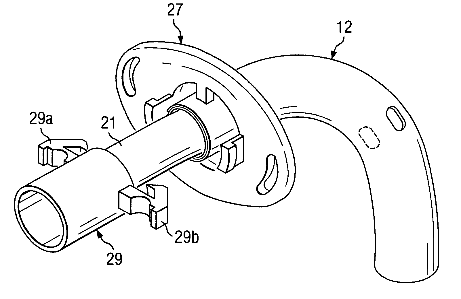
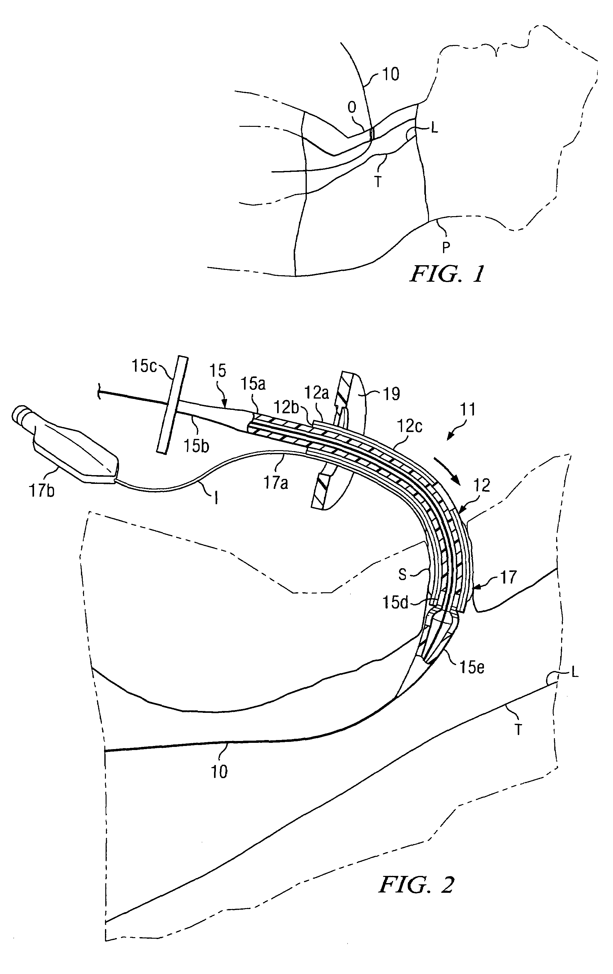
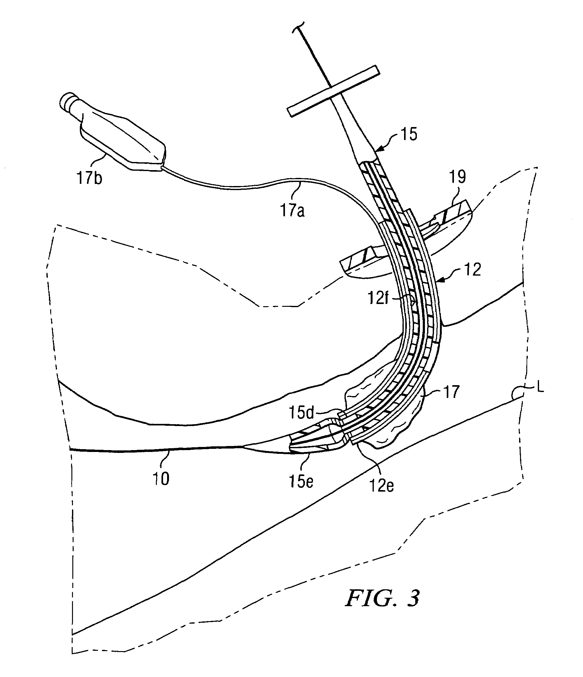
[0026]Referring to the drawings, FIGS. 1-4 illustrate the insertion of the outer, multi-layered tracheostomy tube or element of the tracheostomy system. FIGS. 5-8 illustrate insertion of a cannula of desired size within the outer tracheostomy tube such that the tracheostomy system is fully implanted and operable within the patient.

[0027]Referring to FIG. 1, a general schematic of a patient P is illustrated having trachea T with trachea passage way or lumen L. A guide wire 10 as is known in the art is illustrated as inserted through percutaneous opening O which has been incised in the patient, with the guide wire being fed into the trachea lumen through a needle as is known in the art. It is known to insert the guide wire through the lumen of a needle placed at the incised opening with the aid of a bronchoscope to ensure proper placement of the wire into the lumen of the trachea. After the guide wire is placed, the needle is removed. In FIGS. 1-4, the tracheostomy system generally de...


PUM


Abstract

A tracheostomy system includes an outer multi-layered tube, which can be expanded or allowed to contract as necessary in order to receive various sizes of cannula tubes. A dilator is used to initially insert the outer tracheostomy tube into the tracheostoma. After the initial installation dilator is removed, various sizes of dilators having a cannula mounted about them can be inserted into the outer tracheostomy tube. The multilayered tube will then expand in response to insertion of the various sizes of dilator cannula assembly being placed. When the dilator is removed the cannula tube will remain in place to maintain the desired diameter tracheostomy tube. This provides a means in which the diameter of the tube can be changed without having to actually remove and reinsert a different tube.

Description

CROSS-REFERENCE TO RELATED APPLICATIONS[0001]None.STATEMENTS REGARDING FEDERALLY SPONSORED RESEARCH OR DEVELOPMENT[0002]None.REFERENCE TO A MICROFICHE APPENDIX[0003]None.BACKGROUND OF THE INVENTION[0004]1. Field of the Invention[0005]This invention relates to a new tracheostomy tube and tracheostomy system for performing percutaneous tracheostomy.[0006]2. Description of the Related Art[0007]Percutaneous placement of a tracheostomy is a very common procedure today. It is performed by making a small mid-line incision just over the trachea. Blunt dissection is used to separate the soft tissue down to the level of the tracheal rings. A needle is then placed between adjacent tracheal rings and a guide wire is inserted through the needle, usually under bronchoscopic guidance. Multiple dilators of increasing size or diameters are used to enlarge the ostomy to a sufficient diameter to accommodate the desired-sized tracheostomy tube. Various sizes of tracheostomy tubes are available and are ...

Claims


Application Information

Patent Timeline
Patent Type & Authority Patents(United States)
IPC IPC(8): A61M16/00
CPCA61M16/0465A61M16/0429A61M16/0475
Inventor WOOD, SCOTT DOUGLAS
Owner NBS ACQUISITION
Why Eureka
Try Eureka