Machine for the aseptic treatment of containers in bottling plant

a technology for bottling plants and containers, which is applied in the direction of liquid bottling, closure stoppers, packaging goods types, etc., can solve the problems of difficult management of machines, difficulty in maintaining sterile conditions, and difficulty in reducing distances (i.e. tens of millimeters) and achieves the effect of simple and economical manner

a technology for bottling plants and containers, which is applied in the direction of liquid bottling, closure stoppers, packaging goods types, etc., can solve the problems of difficult management of machines, difficulty in maintaining sterile conditions, and difficulty in reducing distances (i.e. tens of millimeters) and achieves the effect of simple and economical manner

US7341079B2Inactive Publication Date: 2008-03-11SIDEL HLDG & TECH

Image

  • Machine for the aseptic treatment of containers in bottling plant
  • Machine for the aseptic treatment of containers in bottling plant
  • Machine for the aseptic treatment of containers in bottling plant

Examples


Embodiment Construction

[0020]This and other characteristics shall become more readily apparent from the following description of a preferred embodiment illustrated, purely by way of non limiting example in the accompanying drawing tables, in which:

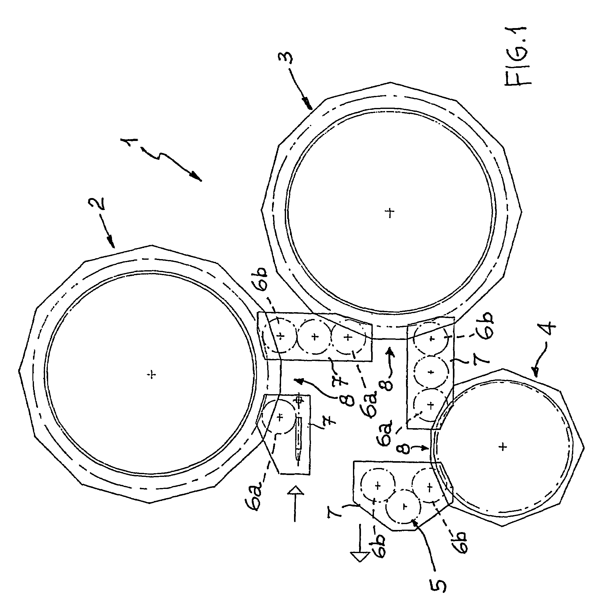
[0021]FIG. 1 schematically shows a plan view of a bottling plant;

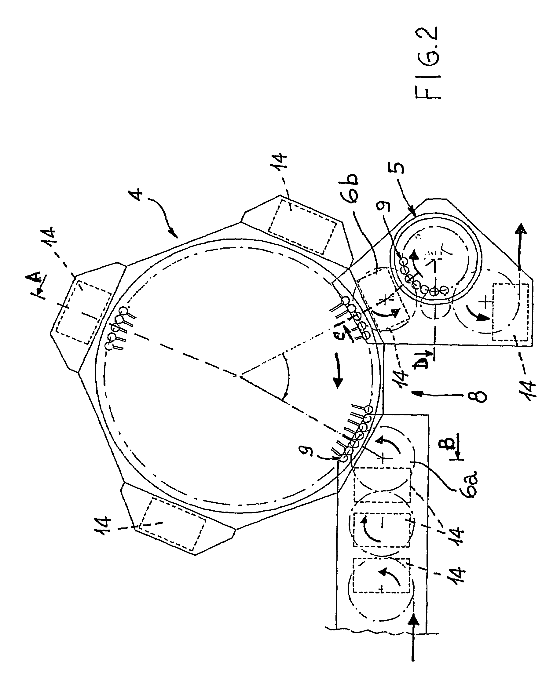
[0022]FIG. 2 shows the filling machine—capping machine set in greater detail;

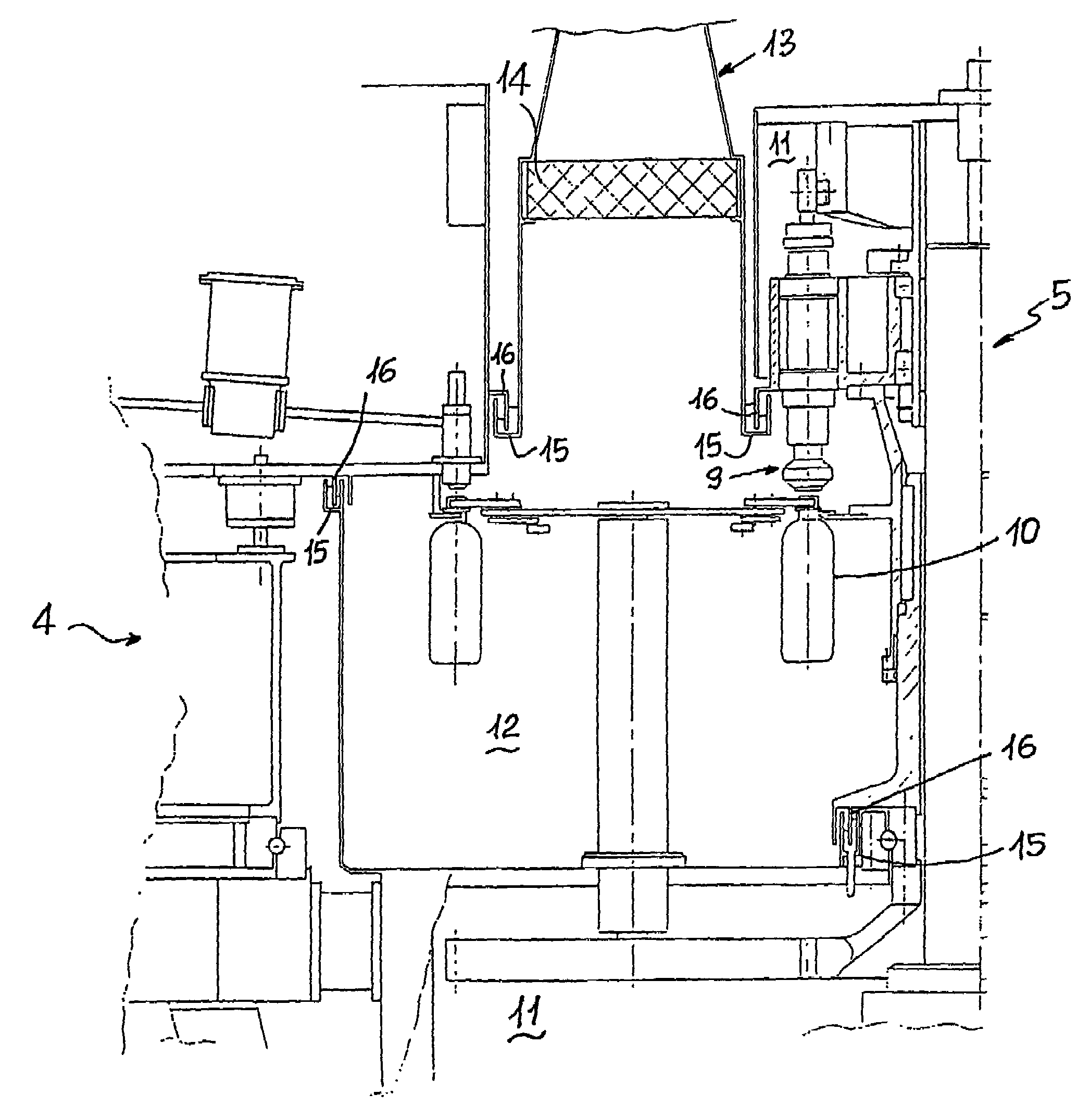
[0023]FIG. 3 shows the section A-B of FIG. 2 relating to the filling machine;

[0024]FIG. 4 shows the section C-D of FIG. 2 relating to the star conveyor between the filling machine and the capping machine;

[0025]FIG. 5 shows a detail of the sealing means and of the central control unit that controls the liquid in the sealing channels.

[0026]With reference to the figures, the reference number 1 globally indicates an aseptic bottling plant comprising a sterilizing machine 2 (for instance of the type that operates by spraying sterilizing solutions), a rinsing machine 3, a filling machine 4 and lastly a capping machine 5, all or ...


PUM

PropertyMeasurementUnit
areaaaaaaaaaaa
dimensionsaaaaaaaaaa
sizeaaaaaaaaaa

Abstract

Machine for the aseptic treatment of containers (10) in bottling plant, of the rotary type provided with a plurality of stations (9) for treating the containers and so shaped as to cause the treatment of the containers to take place under substantially sterile conditions, is characterised in that it comprises sealing means that separate a non sterile area (11) of the machine from an area (12) maintained under sterile conditions and in which the treated containers (10) transit, said means comprising a fixed annular channel (15) at least partially filled with liquid in which slides a concentric annular element (16) associated with the rotating part (11).

Description

CROSS-REFERENCE TO RELATED APPLICATION[0001]This application is a National Stage entry of International Application No. PCT / IT2003 / 000035, filed Jan. 30, 2003, the entire specification claims and drawings of which are incorporated herewith by reference.TECHNICAL FIELD AND BACKGROUND ART[0002]The present invention relates to a machine for the aseptic treatment of containers in bottling plant.[0003]In plants for bottling and packaging containers for drinks (e.g. bottles) under aseptic conditions, to prevent contamination the container treatment area (for instance in the sterilizer, rinsing machine, filling machine, capping machine) must be duly isolated from the exterior environment and maintained sterile.[0004]According to a first constructive solution, the various machines of the plant (e.g. sterilizer, rinsing machine, filling machine, capping machine) are totally inserted inside voluminous aseptic chambers kept in overpressure conditions relative to the exterior environment by usi...

Claims


Application Information

Patent Timeline
11 Mar 2008
Publication
US7341079B2
IPC
B65B1/04; B67C3/22; B67C3/26; B67C7/00
CPC
B67C3/22; B67C7/0073; B67C2003/228; B67C2003/2694
Inventors
ZANGA, FRANCESCO