Moulding device for the production of containers in thermoplastic material

a molding device and thermoplastic material technology, applied in the direction of molds, can solve the problems of large diameter, high mass, insufficient firmness of the top and bottom parts of the mold, etc., and achieve the effects of less bulky, less weight, and less expensive structur

Inactive Publication Date: 2008-03-11
SIDEL PARTICIPATIONS SAS
View PDF8 Cites 15 Cited by
  • Summary
  • Abstract
  • Description
  • Claims
  • Application Information

AI Technical Summary

Benefits of technology

[0010]There is therefore a remaining need for molds with a simplified, less bulky, less heavy, simpler and less expensive structure, this nee

Problems solved by technology

However, in that known arrangement, the hook-shaped lock elements are not distributed over the entire height of the mold which means that the top and bottom parts of the mold are not sufficiently fi

Method used


Image

  • Moulding device for the production of containers in thermoplastic material
  • Moulding device for the production of containers in thermoplastic material
  • Moulding device for the production of containers in thermoplastic material

Examples


Embodiment Construction

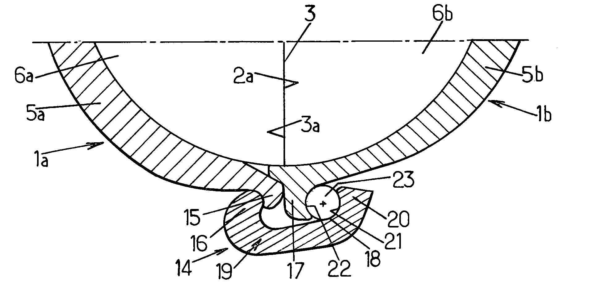
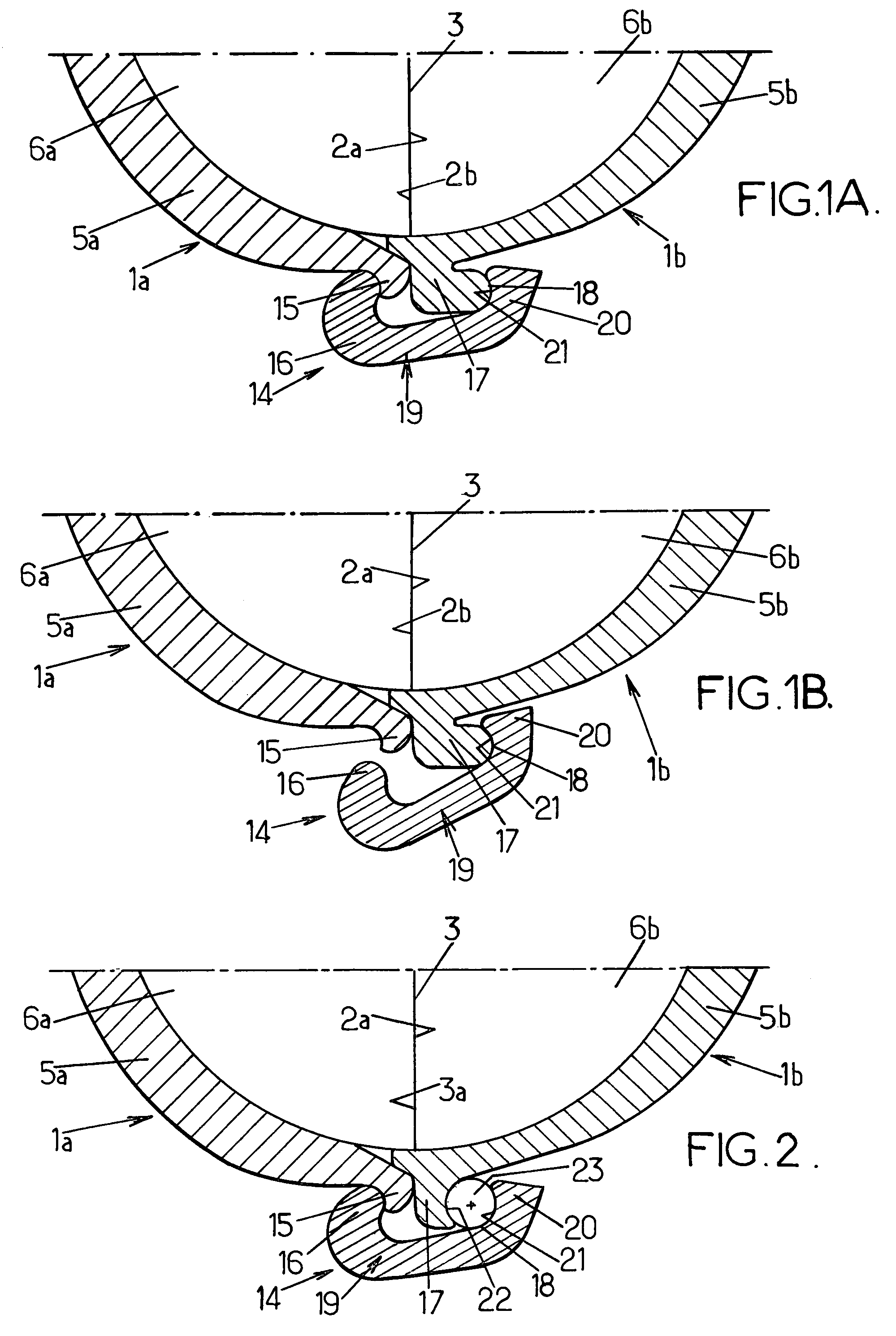
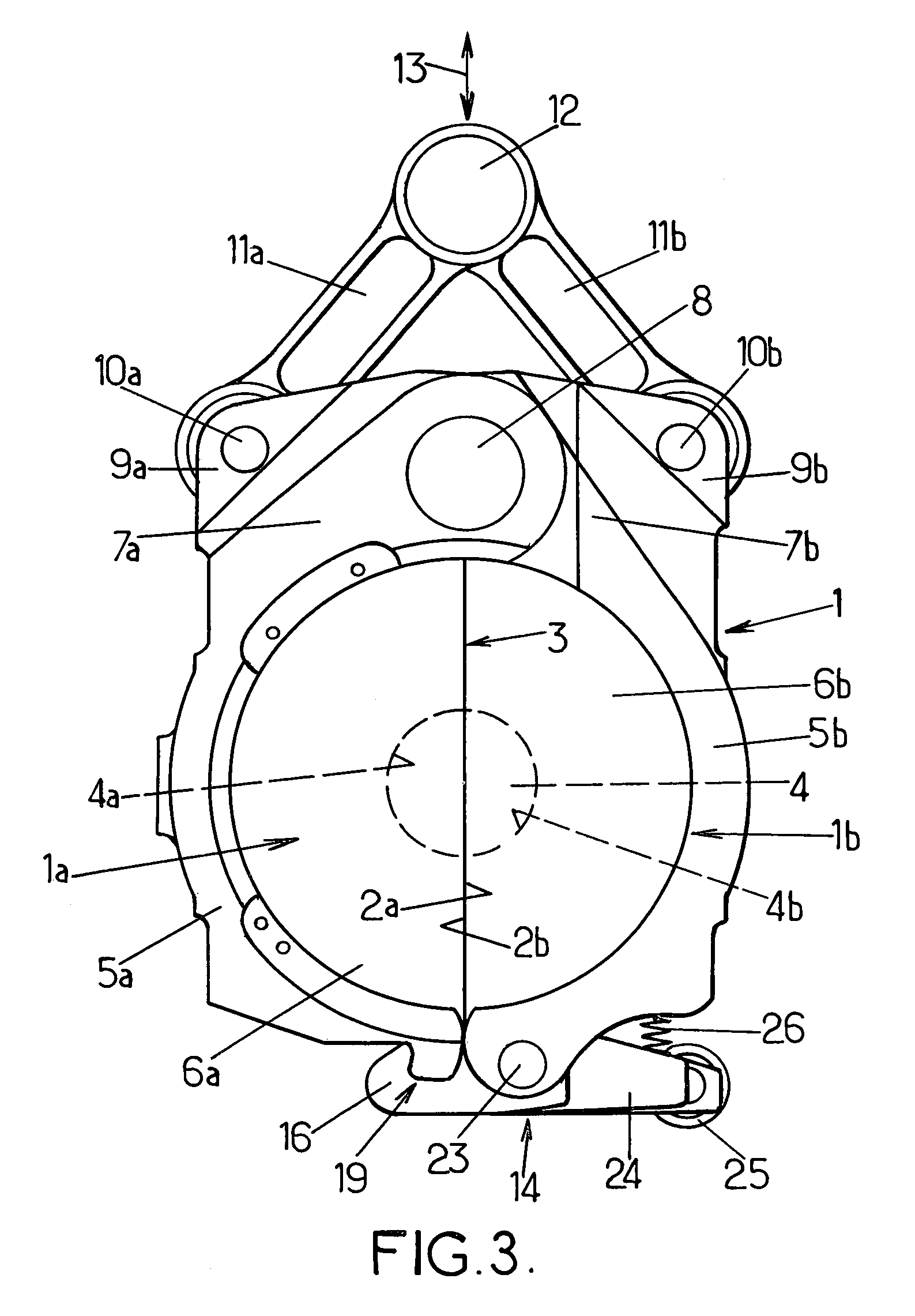
[0040]The arrangements according to the invention are improvements made to molding devices for the blow-molding or stretch-blow-molding of containers, such as bottles, from heated thermoplastic (for example PET) preforms. Such a molding device comprises at least one mold comprising at least two half-molds (and possibly a third part that forms an axially movable mold bottom) which can be moved relative to one another between an open position in which they are parted from one another and a closed position in which they are pressed firmly against one another by collaborating respective faces defining a parting line, locking means being provided to lock the two half-molds in the closed position and prevent them from parting or gaping when the blowing fluid is introduced under very high pressure (for example typically of the order of 40×105 Pa).

[0041]Commonly, such molding devices may comprise a multiplicity of molds and may therefore be arranged in the form of a rotary device or carouse...


PUM

PropertyMeasurementUnit
Pressureaaaaaaaaaa
Shapeaaaaaaaaaa
Radiusaaaaaaaaaa

Abstract

A molding device for the production of containers in thermoplastic material by blowing or blow-drawing, including a mold with two mold halves mutually mobile and provided with a locking device with first and second lock elements, in the form of catches, extending over the whole height of the respective mold halves and a projecting wing on one mold half, including a rotation surface on which a mobile piece is applied over the whole height thereof which includes the second lock element, such that, on blowing, the forces are taken by said mobile piece over the height of the mold by means of the rotation surface.

Description

FIELD OF THE INVENTION[0001]The present invention relates in general to the field of molding devices for blow-molding or stretch-blow-molding containers from heated thermoplastic preforms.[0002]More specifically, the invention relates to improvements made to those of these devices that comprise at least one mold comprising at least two half-molds that can be moved with respect to each other between an open position in which they are parted from one another and a closed position in which they are firmly pressed against one another via collaborating respective bearing faces defining a parting line, locking means being provided to lock the two half-molds in the closed position, which locking means comprising on at least one side of the mold, a first lock element in the form of a hook secured fixedly to the first half-mold along the edge of the bearing face thereof, a second lock element in the form of a hook inverted with respect to the previous one and mounted such that it can pivot, ...

Claims


Application Information

Patent Timeline
IPC IPC(8): B29C49/36B29C49/56B29C33/20B29C33/26B29C49/06
CPCB29C33/202B29C33/26B29C49/56B29C49/06B29C49/36B29K2067/00B29C2049/566B29C2049/5662B29C2949/0715
Inventor LEMAISTRE, ERICLEBLOND, REGIS
Owner SIDEL PARTICIPATIONS SAS
Why Eureka
Try Eureka