Steam-reforming catalytic structure and pure hydrogen generator comprising the same and method of operation of same

a technology of pure hydrogen and catalytic structure, which is applied in the direction of metal/metal-oxide/metal-hydroxide catalyst, combustible gas production, chemical production, etc., can solve the problems of historically limited, costly ceramic catalytic monoliths introduced in automotive catalytic, etc., and achieve less expensive structures and improved hydrogen generation

Active Publication Date: 2003-09-18
HYDRIP LLC
View PDF8 Cites 21 Cited by
  • Summary
  • Abstract
  • Description
  • Claims
  • Application Information

AI Technical Summary

Benefits of technology

0018] More broadly, the principal object of the invention, is to provide a new and improved steam-reforming catalyst structure and hydrogen generator comprising the same and an improved method of such generation that shall not be subject to the above-described and other limitations and disadvantages of the prior, but, to the contrary, provide less expensive structures and improved hydrogen generation.

Problems solved by technology

More recently, costly ceramic catalytic monoliths have been introduced in the automotive catalytic reactors where their low pressure drop (compared to pellet beds) has been a "must".
Membrane reactors have promise to meet these growing demands for distributed hydrogen generation but have been historically limited due to the high palladium content in the membranes.

Method used


Image

  • Steam-reforming catalytic structure and pure hydrogen generator comprising the same and method of operation of same

Examples


example 2

Water Gas Shift Reaction

[0047] The same membrane reactor geometry as in Example 1. The catalyst was WC301B, a proprietary noble metal based water gas shift catalyst supplied by Sud-Chemie, Inc. of Louisville, Ky. The reactor was operated isothermally at 450.degree. C. and at a pressure of 100 psig. The membrane was a 10 micron thick Pd / Cu 60 / 40 wt %. Values are reported to 2 significant figures. Permeate pressure is ambient.

1 Inlet Outlet Permeate Species flow sccm flow sccm flow sccm H.sub.2O 410 260 0 H.sub.2 320 80 390 CO 160 11 0 CO.sub.2 82 230 0 CH.sub.4 11 14 0 [CO.sub.2][H.sub.2] / [CO][H.sub.2O] 0.20 6.4 37.8 (incl. Outlet)

[0048] The equilibrium constant for the WGS reaction at 450.degree. C. is around 11.9. The value of 37.8 represents a temperature of approximately 325.degree. C. Thus the membrane reactor benefit is about 125.degree. C.

example 3

Water gas Shift Reaction

[0049] Same configuration, catalyst, and membrane of Example 2, 350.degree. C. isothermal operation, 100 psig pressure, permeate produced at ambient pressure.

2 Inlet Outlet Permeate Species flow sccm flow scem flow sccm H.sub.2O 540 400 0 H.sub.2 260 90 310 CO 140 4.0 0 CO.sub.2 68 200 0 CH.sub.4 9.2 9.3 0 [CO.sub.2][H.sub.2] / [CO][H.sub.2O] 0.23 11.3 50 (incl. Outlet)

example 4

Methane Steam Reforming

[0050] Same reactor configuration as in Example 3; membrane is 18 microns thick, the catalyst is designated FCR-HC 14, WC-723B also supplied by Sud-Chemie, Inc. of Louisville, Ky. Reaction conditions were 200 psig, 550.degree. C. isothermal operation permeate pressure is ambient.

3 Species Inlet flow sccm Outlet flow sccm Permeate flow sccm H.sub.2O 270 120 0 H.sub.2 0 9.0 310 CO 0 9.0 0 CO.sub.2 0 70 0 CH.sub.4 120 40 0

[0051] Note that the expected CH.sub.4 conversion at equilibrium under these conditions of temperature and pressure is only 17% compared to 67% in this case. To achieve the same 67% conversion of methane in an ordinary reactor at these conditions would require a temperature of about 860.degree. C. Thus a temperature lowering benefit of nearly 300.degree. C. is realized in the membrane reactor.


PUM

PropertyMeasurementUnit
temperatureaaaaaaaaaa

Abstract

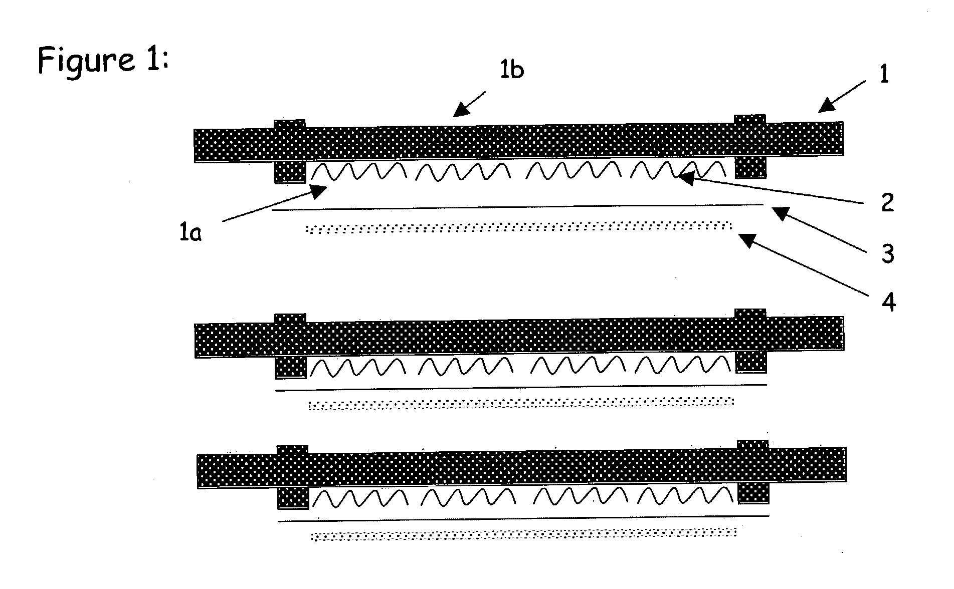
A reactor/purifier for generating pure hydrogen in a stack or array of pairs of alternatingly connected high and low pressure reactor chambers wherein a gas-porous turbulence-promoting screen structure washcoated with a steam-reforming catalyst is sandwiched between a planar hydrogen-selective palladium alloy membrane and a planar gas-impermeable heat-conducting metal plate within the high pressure reactor chamber of each high pressure reactor chamber; and wherein the catalyst-coated structure in each high pressure chamber is reacted with steam and hydrocarbon fuel, such as methane or syn/gas, and/or carbon monoxide at an appropriately controlled temperature of between about 200° C. to 650° C. to produce hydrogen and carbon oxides within an isothermal temperature range in each high pressure reactor chamber, while simultaneously permeating pure hydrogen therefrom through the membrane into the corresponding connected low pressure reactor chamber, and with the required heat transfer to and from the catalyst being provided in situ predominantly by conduction through the corresponding metal plate.

Description

[0001] The present invention relates broadly to steam-reforming catalytic structures and hydrogen generation, being more particularly concerned with novel unitary catalytic structures and methods for generating hydrogen by reacting steam with a gaseous or gasified fossil hydrocarbon fuel and the like at a moderately elevated temperature, and still more particularly with palladium-bearing membrane pure hydrogen generators comprising the same.[0002] As explained in provisional patent application No. 60 / 363,672, filed Mar. 12, 2002, and on the basis and priority of which this application is filed, the prior art is replete with descriptions of catalysts for producing hydrogen by the reaction of steam (herein "steam reforming"), at moderately elevated temperatures, with gaseous or gasified fossil fuels including natural gas, propane, methanol, carbon monoxide (e.g. made by partial oxidation of coal) and mixtures comprising carbon monoxide and hydrogen (herein "syn-gas") and derivatives t...

Claims


Application Information

Patent Timeline
Patent Type & Authority Applications(United States)
IPC IPC(8): B01D53/22B01D63/08B01D69/10B01D71/02B01J19/24B01J23/76B01J23/83B01J35/02B01J35/06B01J35/10B01J37/03C01B3/16C01B3/32C01B3/38C01B3/50
CPCB01D53/22H01M8/0687B01D63/08B01D2313/42B01J19/2475B01J19/249B01J19/2495B01J23/83B01J35/1014B01J37/03B01J2219/00157B01J2219/2451B01J2219/2453B01J2219/2458B01J2219/2461B01J2219/2462B01J2219/2465B01J2219/2467B01J2219/2475B01J2219/2479B01J2219/2482B01J2219/2485C01B3/16C01B3/323C01B3/38C01B3/501C01B2203/0233C01B2203/0283C01B2203/041C01B2203/1035C01B2203/1223C01B2203/1241H01M8/0618H01M8/0668B01D53/228Y02P20/52Y02E60/50
Inventor KRUEGER, CHARLES W.
Owner HYDRIP LLC
Why Eureka
Try Eureka