Successive approximation analog/digital converter

a technology of analog/digital converter and approximation, which is applied in the field of analog/digital converter, can solve the problems of inability to arbitrarily shorten the conversion time and hence the conversion time of an analog input value into a digital output value, the need for a relatively large proportion of input drivers, and the power loss is also relatively high, so as to achieve fast analog/digital conversion, reduce power loss, and high capacity

Inactive Publication Date: 2008-03-11
INFINEON TECH AG
View PDF13 Cites 7 Cited by
  • Summary
  • Abstract
  • Description
  • Claims
  • Application Information

AI Technical Summary

Benefits of technology

[0012]The idea on which the present invention is based is to provide a successively operating A / D converter with more than just one comparator. These comparators are comparators which are connected in parallel with one another and are therefore designed to operate in parallel with one another too and hence to perform a respective conversion in parallel. These parallel-connected and parallel-operating comparators are used to define a number of comparator thresholds which corresponds to the number of these comparators. For this, the capacitive network of the A / D converter needs to be accordingly divided into a plurality of capacitive subnetworks. The particular advantage here is that the use of a plurality of comparators allows the overall A / D conversion to be made faster without this having significant drawbacks in terms of power loss, since the proportion of the power loss in the comparator relative to the capacitive network turns out to be very small.
[0013]Unlike previously known successive approximation A / D converters, the inventive successive approximation A / D converter requires a smaller number of conversion cycles for ascertaining the converter result, since a larger number of comparators is available for this ascertainment of the converter result. Since more than one bit of the output signal can therefore be determined per conversion cycle, the conversion rate of the inventive A / D converter is significantly faster than in the case of previously known successive approximation A / D converters.
[0019]The second comparator stage may also have a larger number of comparators than the respective upstream comparator stage. In this arrangement, the comparators in the second comparator stage are logically combined at least to some extent through interpolation with the comparators in the respective upstream comparator stage, which allows a larger number of comparator thresholds and hence faster analog / digital conversion to be provided.
[0026]The inventive analog / digital converter may be in the form of a ‘redundant analog / digital converter’, which is advantageous particularly in terms of a higher converter speed.

Problems solved by technology

Nevertheless, the conversion speed and hence the conversion time for converting an analog input value into a digital output value cannot be shortened arbitrarily in the case of a successive approximation A / D converter.
In addition, its power loss is also relatively high on account of the influence of the input drivers.
A similarly disadvantageous characteristic is the need for the input driver to be given relatively large proportions on account of the great influence of parasitic capacitances on the input side.
However, a cascade converter has an unfavorable characteristic, particularly when using a multistage cascade converter and an associated large number of input capacitances, since the noise requirements in the case of a cascade converter require a very high level of capacity to be provided for every single input capacitance, and this complexity can increase the associated complexity exorbitantly, particularly with a large number of input capacitances.

Method used


Image

  • Successive approximation analog/digital converter
  • Successive approximation analog/digital converter
  • Successive approximation analog/digital converter

Examples


Embodiment Construction

[0033]In the figures of the drawing, elements, features and signals which are the same or have the same function have been provided with the same reference symbols—unless stated otherwise.

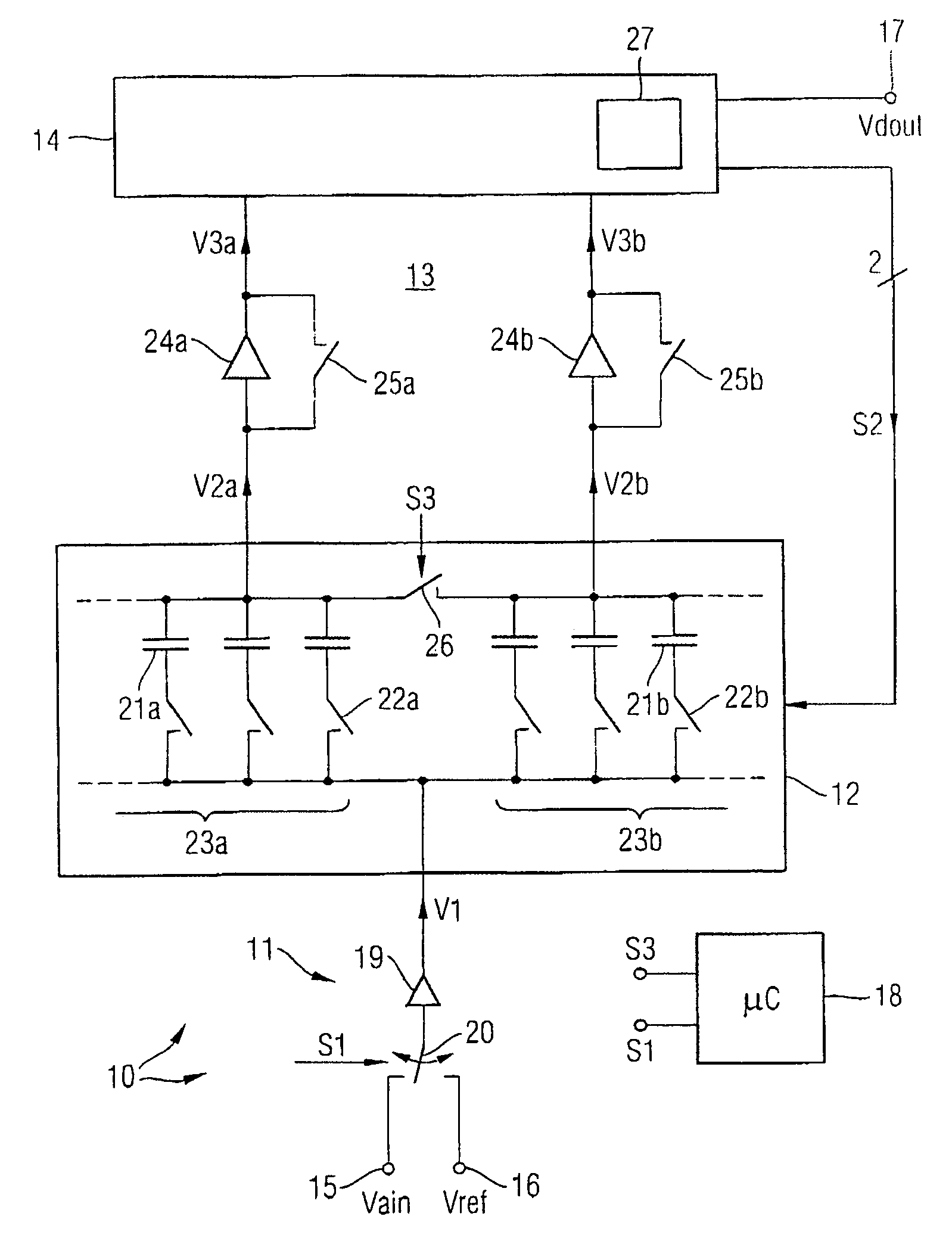
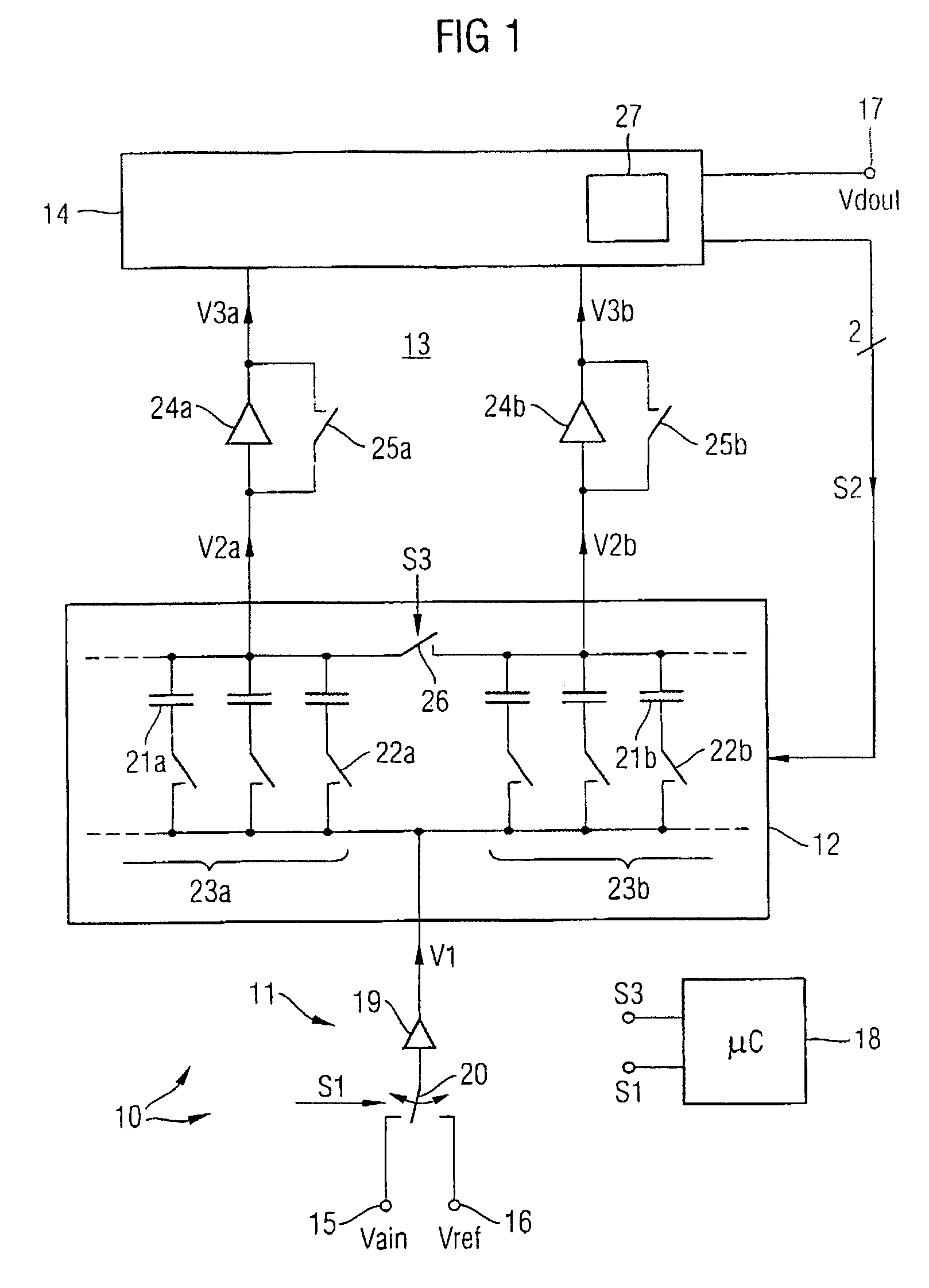
[0034]FIG. 1 shows a block diagram of a first general exemplary embodiment of an inventive successive approximation A / D converter.

[0035]The A / D converter in FIG. 1 is denoted by reference symbol 10. In FIG. 1, the A / D converter 10 shown therein is first of all shown in nondifferential form, but this could very easily also be shown in differential form.

[0036]The A / D converter 10 essentially has an input buffer circuit 11, a capacitive network 12, a comparator stage 13 and a logic circuit 14. These circuit parts 11-14 of the A / D converter 10 are arranged between inputs 15, 16 and an output 17. In addition, a control device 18 is provided which can be used to control the function of the A / D converter 10.

[0037]A first input 15 can have the analog input signal Vain which is to be converted into a digita...


PUM


Abstract

A successive approximation analog / digital converter converting an analog input signal into a digital output value by means of a plurality of successive conversion cycles, comprises at least one first input for injecting an analog input signal, a controllable capacitive network which is connected downstream of the first input and which is divided into at least two capacitive subnetworks and, at least two parallel-connected and parallel-operating comparators for defining a number of comparator thresholds which corresponds to the number of parallel comparators. The comparators are respectively connected downstream of one of the capacitive subnetworks and the comparators output a corresponding number of digital intermediate signals on the basis of the comparisons in the comparators. The analog / digital converter further comprises a register set by the intermediate signals. The register buffer-stores digital intermediate values for the respective intermediate signals and produces control signals for actuating the capacitive subnetworks in response to the content of the intermediate signals.

Description

BACKGROUND OF THE INVENTION[0001]The present invention relates to an analog / digital converter.[0002]Analog / digital converters—frequently also called A / D converters—are electronic circuits which convert an analog input variable, for example an input voltage or an input current, into a proportional digital output variable, which are able to be output as a binary thermometer code encoded output signal, for example. Many kinds of A / D converter types are known for analog / digital conversion, for example parallel operation A / D converters (flash converters), cascade A / D converters (subranging converters), and A / D converters operating on the basis of the weighing process or the principle of successive approximation (in this regard see Tietze, Schenk, Halbleiterschaltungstechnik [Semiconductor circuitry], 10th edition, particularly pages 780 ff).[0003]The process of successive approximation involves the data bits of a digital output variable being determined successively one after the other f...

Claims


Application Information

Patent Timeline
Patent Type & Authority Patents(United States)
IPC IPC(8): H03M1/34
CPCH03M1/403
Inventor KUTTNER, FRANZ
Owner INFINEON TECH AG
Why Eureka
Try Eureka