

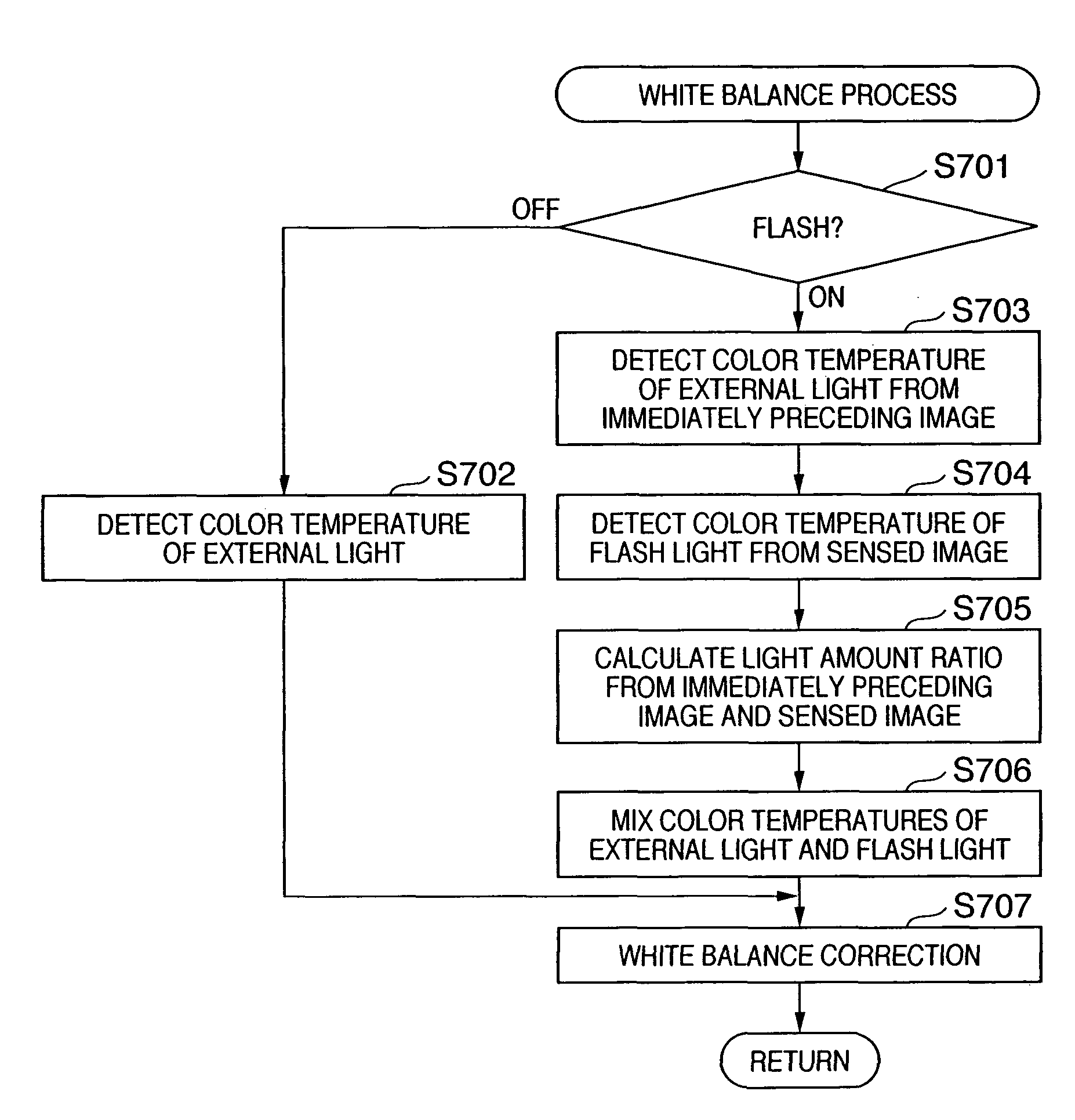
Color balance adjustment of image sensed upon emitting flash light
- Summary
- Abstract
- Description
- Claims
- Application Information
AI Technical Summary
Benefits of technology
Problems solved by technology
Method used
Image

Examples
Embodiment Construction
[0021]A preferred embodiment of the present invention will now be described in detail in accordance with the accompanying drawings.
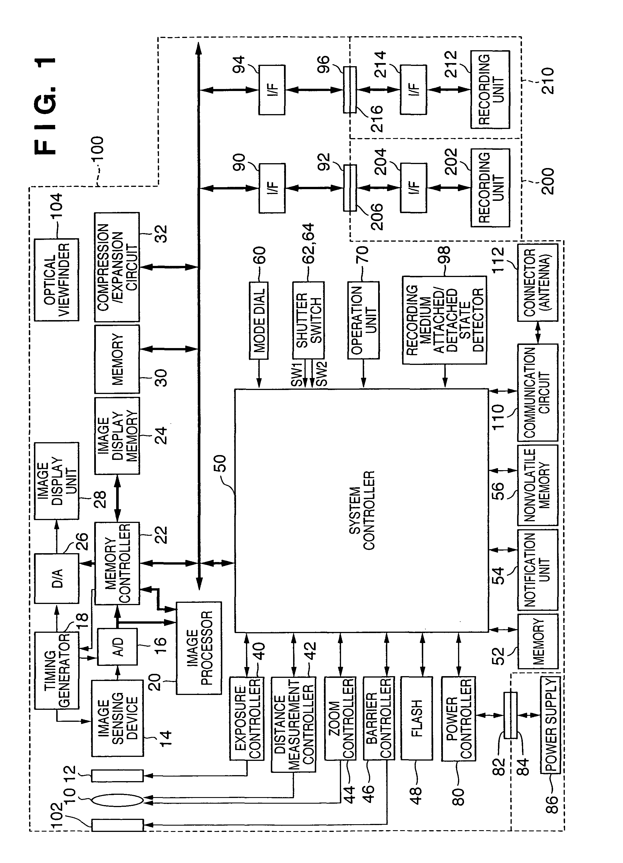
[0022]FIG. 1 is a block diagram showing the arrangement of an image sensing apparatus with an image processing function according to an embodiment of the present invention.
[0023]Referring to FIG. 1, reference numeral 100 denotes an image sensing apparatus. Reference numeral 10 denotes an image sensing lens; 12, a shutter having a diaphragm function; 14, an image sensing device which converts an optical image into an electrical signal; and 16, an A / D converter which converts an analog signal output from the image sensing device 14 into a digital signal.
[0024]Reference numeral 18 denotes a timing generator which supplies a clock signal and control signal respectively to the A / D converter 16 and a D / A converter 26 under the control of a memory controller 22 and system controller 50.
[0025]Reference numeral 20 denotes an image processor which executes a prede...
PUM
 Abstract
Description
Claims
Application Information