
Automatic color balance

a color balance and automatic technology, applied in the field of computer assisted imaging, can solve the problems of inability to achieve uniform color, inability to achieve the effect of uniform color, and inability to achieve the effect of uniform image contrast, automatic correction of image color balance, and substantially unchanged image contras

Active Publication Date: 2006-06-06
COREL CORP +1
View PDF30 Cites 40 Cited by
  • Summary
  • Abstract
  • Description
  • Claims
  • Application Information

AI Technical Summary

Benefits of technology

[0012]It is an aspect of this invention to provide a method of color correction for digital images. A further aspect of the invention is to provide a method of removing strong color casts from images. Another aspect of the invention is to provide a means of automatically correcting color balance in images. Yet another aspect of the invention is to correct color balance in an image by a means that allows compensation for the color of the scene illuminant. Still another aspect of the invention is to provide a method of color correction that leaves image contrast substantially unchanged.

Problems solved by technology

Since none of the devices produce consistently perfect color, especially in the hands of unskilled amateurs, there is a need to correct the color of images.
However, these methods fail when detector saturation occurs since the brightest pixels then no longer represent the illuminant and, except for the Usami procedure, are computationally expensive.
These methods are computationally intensive an do not uniquely identify the illuminant with additional assumptions.
However, this method fails when the scene content does not, in fact, correspond to an average gray.
None of these methods are, however, fully satisfactory because of failure of the gray world assumption.
However, such approaches are useless when the images to be processed do not fall into a few simple categories.
Such methods frequently fail when they encounter images not in the original training set.
Moreover, the effort of developing such a method is very great because of the large number of images on which it is based and the resulting method is hard to understand and modify because of its complexity.
In the case of neural networks, there is a danger of over-training, where correction of the training set improves at the expense of generality in the correction performance.
Most of these methods place particular emphasis on the highlight and shadow regions of the histogram though some, such as U.S. Pat. No. 6,151,410, specifically exclude some of these regions on the grounds that the data are unreliable.
These methods depend on the image data set used to derive the statistical analysis of the histogram and can be unsatisfactory for images of a type not in the original data set.
At least some cause over-correction of the image when applied repeatedly and can result in information loss through clipping of the lowest and highest intensities in the image.
These methods are, further, inherently incapable of correcting for different scene illuminants.
These methods, however, require manual intervention and it can be difficult to select the optimal black and white points to achieve the desired correction.
These methods have the disadvantage that part of the image information is lost through the clipping process and, further, image contrast is undesirably changed along with the correction of color.
This procedure, however, has the disadvantage that the color correction can depend on as few as two pixels in the image.
This renders the method susceptible to noise and to defective pixels in digital camera detectors.

Method used


Image

  • Automatic color balance
  • Automatic color balance
  • Automatic color balance

Examples


first embodiment

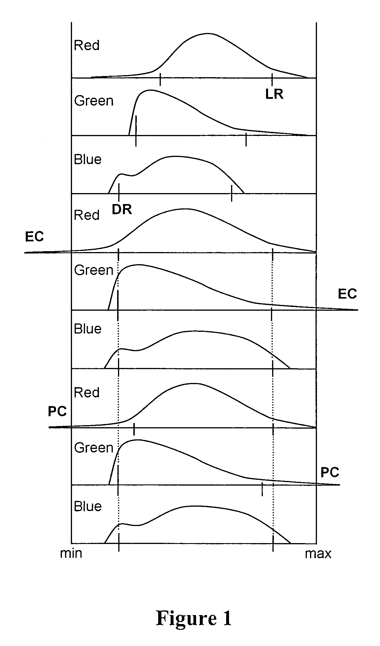
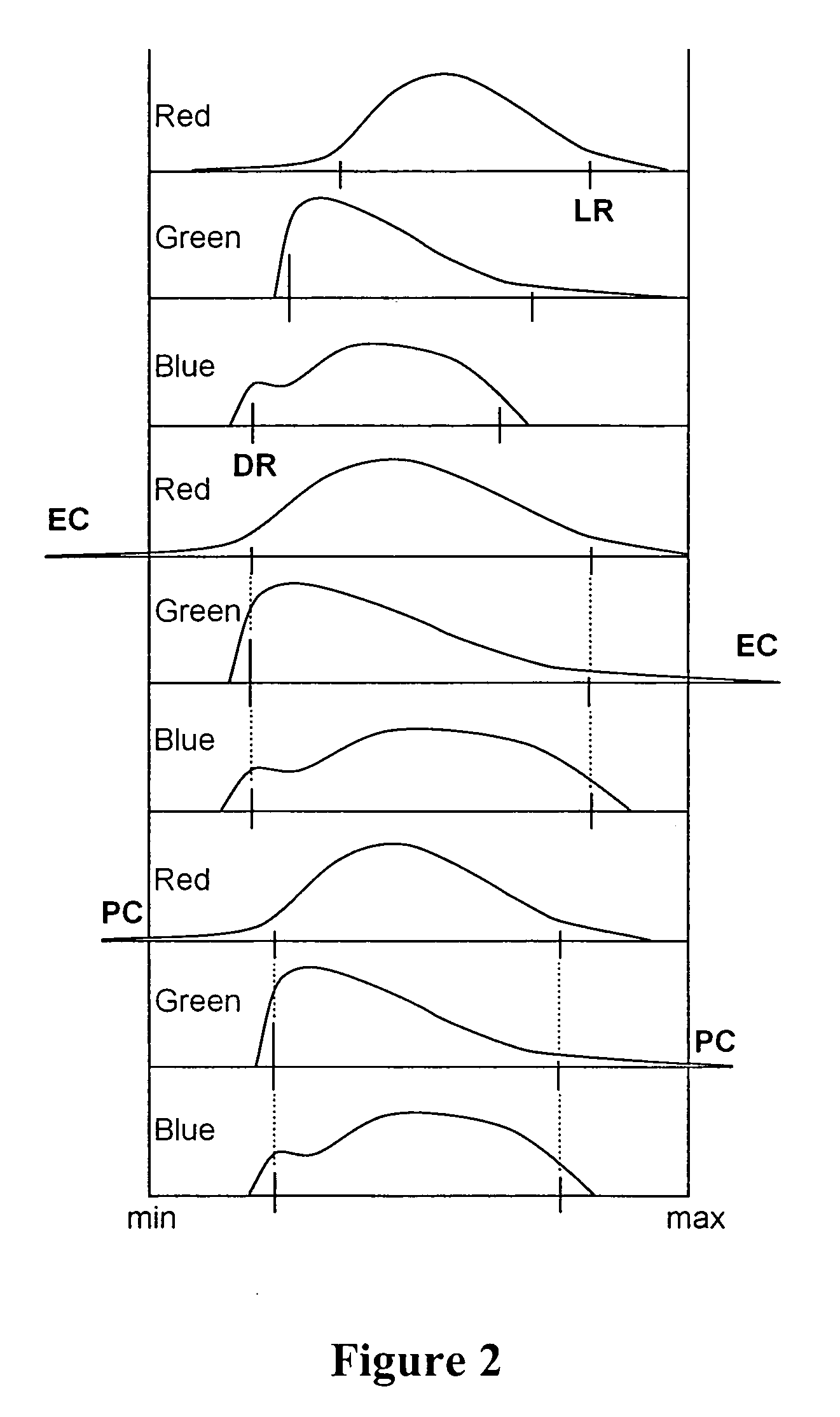
[0053]This embodiment is suitable for processing the majority of normal images that required color balancing, especially when it is desired to perform the correction automatically without user intervention. In the shadow region each of the control points Rlow, Glow, Blow that lies above Xlow is moved towards the reference point Xlow, subject to the condition that the clipping fraction is not exceeded. Thus, if a particular channel does not exceed the predetermined clipping fraction its control point is aligned with Xlow. Otherwise, the channel value of the histogram that corresponds to the clipping fraction becomes aligned with Xlow. The judgement of clipping is done channel by channel, without regard to the amount of clipping in other color channels. Similarly, in the highlight region each of the control points Rhigh, Ghigh, Bhigh that lies below Xhigh is moved towards the reference point Xhigh, subject to the condition that the clipping fraction is not exceeded. Thus, if a particu...

second embodiment

[0054]This embodiment, referred to as the color cast correction, is suitable for processing the majority of normal images that require color balancing and in addition is useful for images that exhibit strong color errors in the form of a distinct color cast. It can also be applied to the automatic correction of images without user intervention. The procedure will be described in two steps for clarity but, as will be appreciated by those skilled in the art, it can also be accomplished in a single step. In step 1, for the shadow region each of the control points Rlow, Glow, Blow is moved into exact alignment with the reference point Xlow. (Note that one color control point is already coincident with Xlow as it was used to determine Xlow). Similarly, in the highlight region each of the control points Rhigh, Ghigh, Bhigh is moved into exact alignment with the reference point Xhigh. This may result in one or more of the color channels being clipped by more than the permitted clipping fra...

third embodiment

[0055]Following the correction according to the first or the second embodiment of the invention the color of the resulting image is well balanced. However, the true color of the scene, especially of neutral gray or white in the scene, may not correspond to the light source used to image the scene. Thus, a scene illuminated with summer skylight of color temperature 9500K would lead to a bluish white. The same scene illuminated with average summer sunlight with some skylight at a color temperature of 6500 K would give rise to a neutral white. Illumination with a flash lamp of color temperature 5000K would produce a yellowish white and an incandescent lamp of 2900K would yield a more orange white. In some cases it is advantageous to restore the appearance of the original scene illuminant even though, strictly speaking, the colors are no longer balanced. There are many ways of achieving this objective as will be obvious to those skilled in the art. One method that has been found effecti...


PUM

PropertyMeasurementUnit
color temperatureaaaaaaaaaa

Abstract

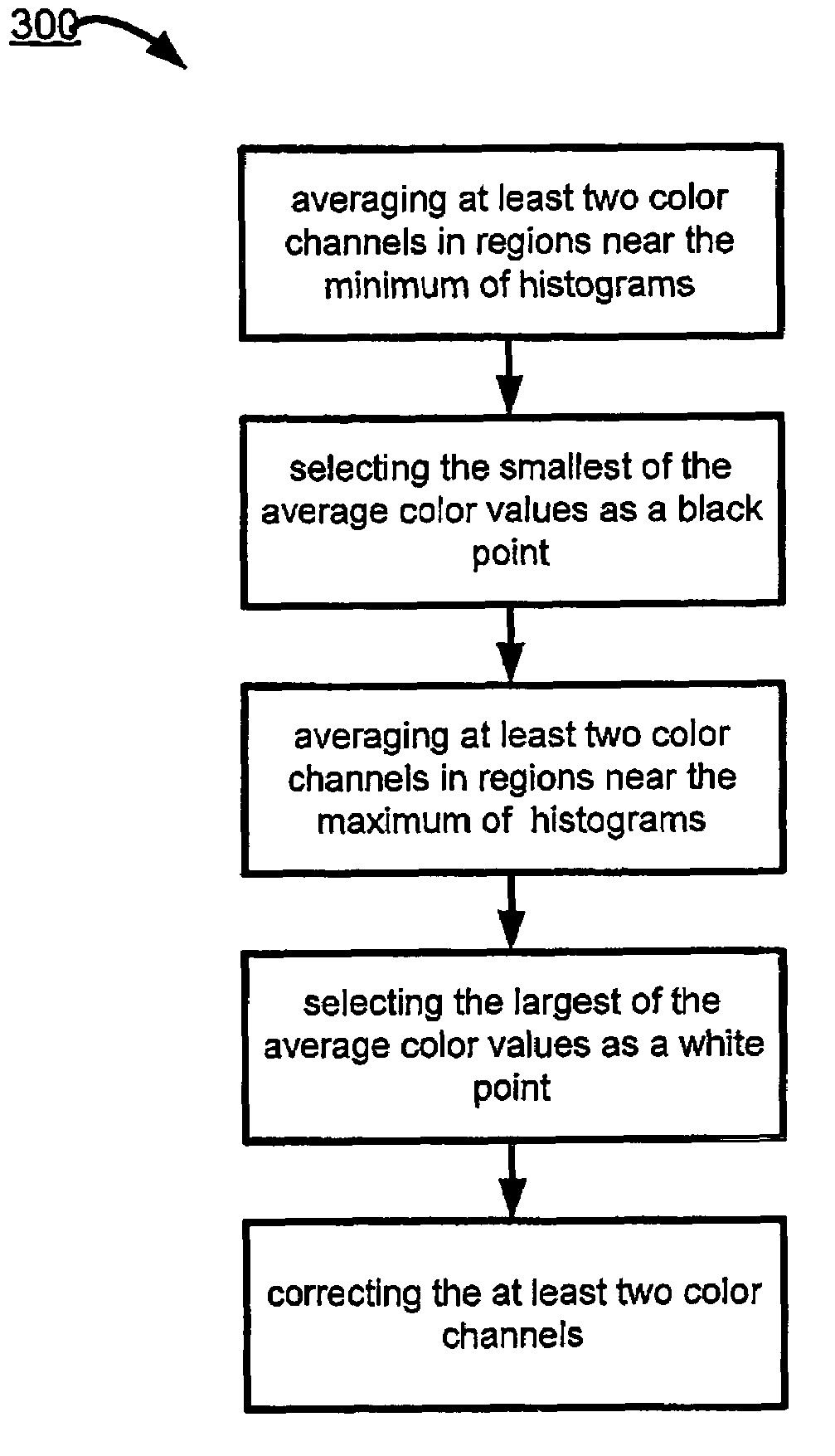
A method corrects a color image by avenging at least two color channels in regions near the minimum of histograms of the at least two color channels; selecting the smallest of the avenge color values as a black point; averaging at least two color channels in regions near the maximum of the histograms of the at least two color channels and selecting the largest of the avenge color values as the white point; and correcting the at least two color channels by adjusting the smallest and the largest color averages to respectively match the valves of the black point and the white point to form corrected image data. A preferred method limits the adjustment to a predetermined amount of clipping of the at least two color channels.

Description

BACKGROUND OF HE INVENTION[0001]1. Field of the Invention[0002]The present invention relates to the field of imaging, the field of computer assisted imaging, the field of digital imaging, and the field of automatically controlled enhancement of specific attributes of digital imaging data such as contrast.[0003]2. Background of the Invention[0004]The proliferation of digital imaging means such as photography, scanning, copying, printing and digital cameras has resulted in a large volume of color imagery. Since none of the devices produce consistently perfect color, especially in the hands of unskilled amateurs, there is a need to correct the color of images. Color correction has been the object of much effort in the imaging art but there remains a need for simple correction methods that can be applied in an automated way.[0005]One approach to correcting color is based on the idea that improper colors in the scene are the result of illumination that is not perfectly white. If the illu...

Claims


Application Information

Patent Timeline
Patent Type & Authority Patents(United States)
IPC IPC(8): G06F15/00B41J1/00G03F3/08G06K9/00H04N1/60H04N9/73
CPCH04N1/6008H04N9/735H04N1/6077H04N23/88
Inventor ZAKLIKA, KRYZSTOF ANTONITATARNIKOV, MIKHAIL EVGEN'EVICHMAKULOV, VASSILY BORISOVICH
Owner COREL CORP
Learn More