
Dichroic beam combiner utilizing blue LED with green phosphor

a combiner and blue led technology, applied in semiconductor devices, lighting and heating apparatus, instruments, etc., can solve the problems of difficult to distinguish red vs. green objects, peak candlepower limit of a given headlamp size, poor color rendition, etc., to achieve superior performance, high color rendering index, and high luminance

Active Publication Date: 2005-06-02
LIGHT PRESCRIPTIONS INNOVATORS
View PDF29 Cites 66 Cited by
  • Summary
  • Abstract
  • Description
  • Claims
  • Application Information

AI Technical Summary

Benefits of technology

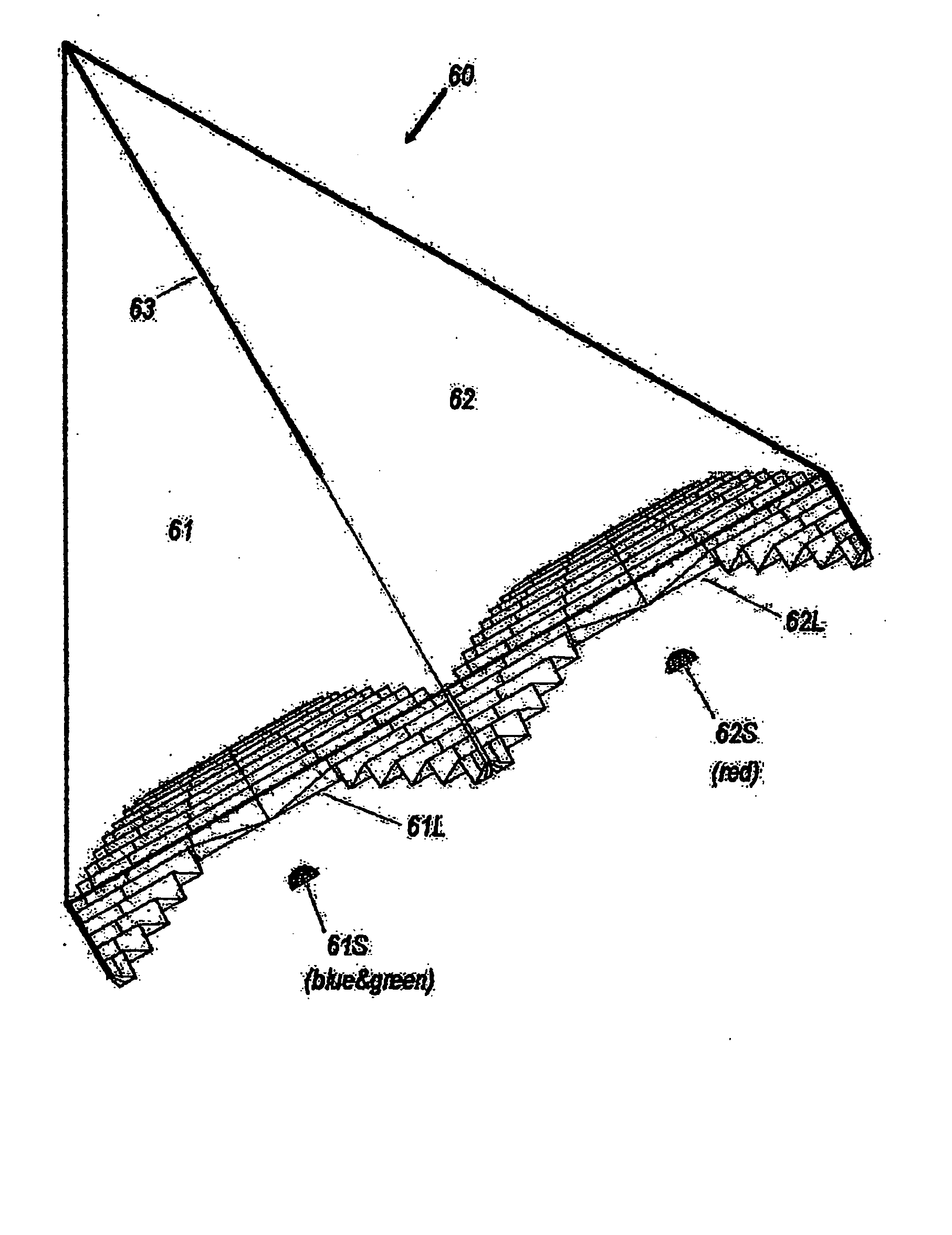
[0010] The green phosphor of the present invention operates near the 555 nm wavelength of peak luminous efficacy (683 lumens / watt). It necessarily produces more lumens than a yellow phosphor of the same quantum efficiency. A green phosphor coating on a high-power blue LED can be given the requisite thickness for proper color balance with a high-power red LED. The present invention advantageously combines these two wavebands into a white resultant with high color-rendering index as well as higher luminance than possible solely with a white LED based on the same blue chip. This superior performance is because of the higher luminance of a blue LED with green phosphor being efficiently combined with the additional luminance of a red LED with separate cooling means. The linear nature of the prism allows long arrays of such red-blue LED pairs to be utilized for very powerful vehicular lighting. In the case of police vehicles, switching off either set of LEDs would produce either a red or a cyan light, the latter being close to the conventional blue of police emergency lights. Such a long prism is easily swiveled to vertically steer the high-intensity output beam.

Problems solved by technology

For illumination, however, two wavelengths give poor color rendition, making it difficult to distinguish red vs. green objects, in the case of a yellow-blue pair of LEDs combined by a green dichroic reflector, or green vs. magenta objects, in the case of a red-cyan pair combined by an amber dichroic reflector.
Such LEDs will soon be applied to automobile headlamps, but their peak luminance sets the peak candlepower limit for a given headlamp size.

Method used


Image

  • Dichroic beam combiner utilizing blue LED with green phosphor
  • Dichroic beam combiner utilizing blue LED with green phosphor
  • Dichroic beam combiner utilizing blue LED with green phosphor

Examples


Embodiment Construction

[0021] A better understanding of the features and advantages of the present invention will be obtained by reference to the following detailed description of the invention and accompanying drawings, which set forth illustrative embodiments in which the principles of the invention are utilized.

[0022] The following description of the presently contemplated best mode of practicing the invention is not to be taken in a limiting sense, but is made merely for the purpose of describing the general principles of the invention. The scope of the invention should be determined with reference to the claims.

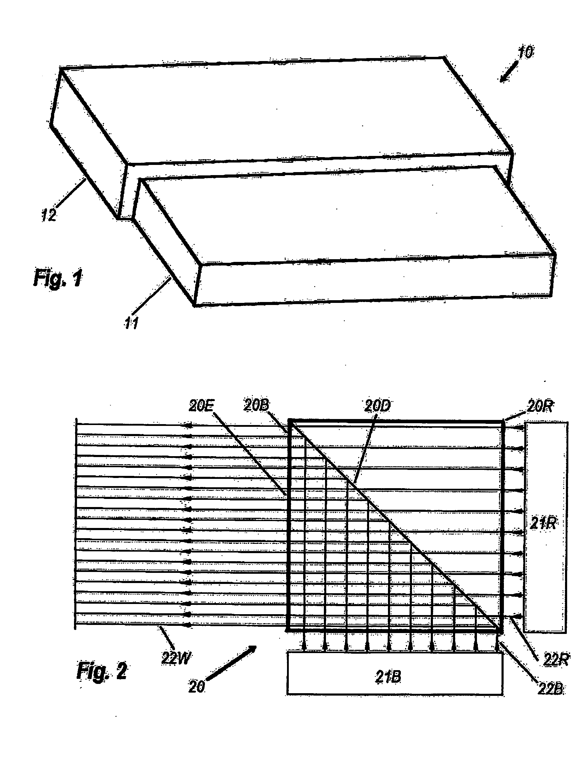
[0023]FIG. 1 schematically depicts coated LED 10 comprising blue LED 11 and green phosphor coating 12.

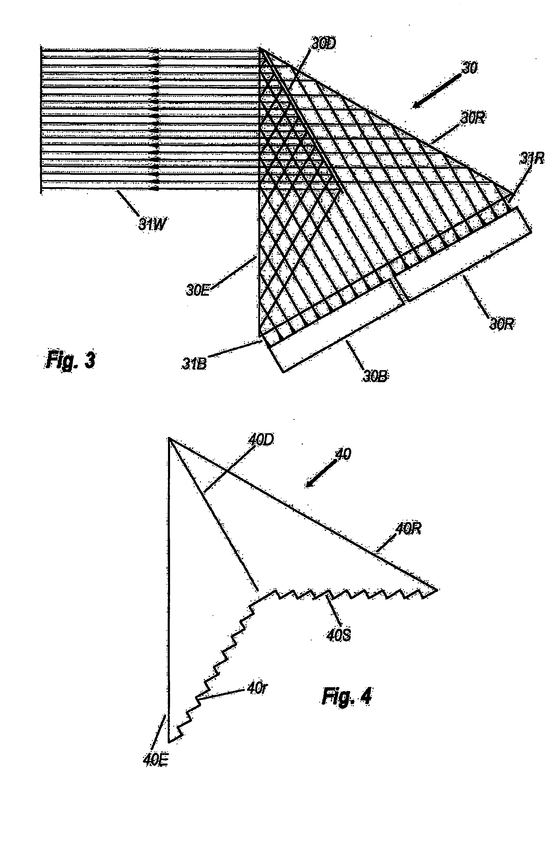
[0024]FIG. 2 depicts prism 20 comprising isosceles half-square prism 20B and congruent prism 20R, both joined along dichroic interface 20D. Collimator 21R emits substantially parallel red rays 22R, which pass with high transmittance through filter 20D, thereafter to exit prism 20 via exit f...


PUM


Abstract

A white beam with high color-rendering index is formed by uniting a collimated red beam and a collimated blue−green beam, the latter having as its source a blue LED with a green phosphor. The white beam is formed by a prism with an amber low-pass dichroic filter. The prism cross-section can be either a square or an equilateral triangle. The triangular prism can have one third of its mass reduced by stepped facets. Both types of prism can be elongated to accommodate multiple collimators. Switching between white, red, and blue−green allows application to police vehicles.

Description

[0001] This application claims priority under 35 U.S.C. 119(e) to U.S. Provisional Patent Application No. 60 / 520,513 filed Nov. 14, 2003, of Minano, et. al., for DICHROIC BEAM COMBINER UTILIZING BLUE LED WITH GREEN PHOSPHER, which U.S. Provisional Patent Application is hereby fully incorporated herein by reference.BACKGROUND OF THE INVENTION [0002] One the several ways of using light-emitting diodes (LEDs) to make white light is separately generating three differently colored wavebands and subsequently combining them. This has the advantage of each color source being separately cooled, so that the combined luminous output of the three LEDs is potentially higher than that of one. One example of a single LED producing white light is a blue LED coated with a yellow phosphor, such as those produced by Lumileds and by Nichia. [0003] Dichroic beam combining systems are found in television, particularly those utilizing dichroic prisms and even crossed dichroic prisms, containing two dichro...

Claims


Application Information

Patent Timeline
Patent Type & Authority Applications(United States)
IPC IPC(8): G02BG03B21/28
CPCF21K9/00F21K9/52F21Y2101/02G02B19/0061G03B21/204Y10S362/80G02B19/0028G03B33/12F21K9/61F21K9/69F21Y2115/10
Inventor MINANO, JUAN CARLOSBENITEZ, PABLOPARKYN, WILLIAM A. JR.
Owner LIGHT PRESCRIPTIONS INNOVATORS
Learn More