
Method and system for generating a bitstream view of a design

a bitstream view and design technology, applied in the field of programable logic devices, can solve the problems of a variety of infirmities, difficult to distinguish between unused configuration bits and essential configuration bits that retain their default value, and fairly intractable problems

Active Publication Date: 2008-03-11
XILINX INC
View PDF12 Cites 23 Cited by
  • Summary
  • Abstract
  • Description
  • Claims
  • Application Information

AI Technical Summary

Benefits of technology

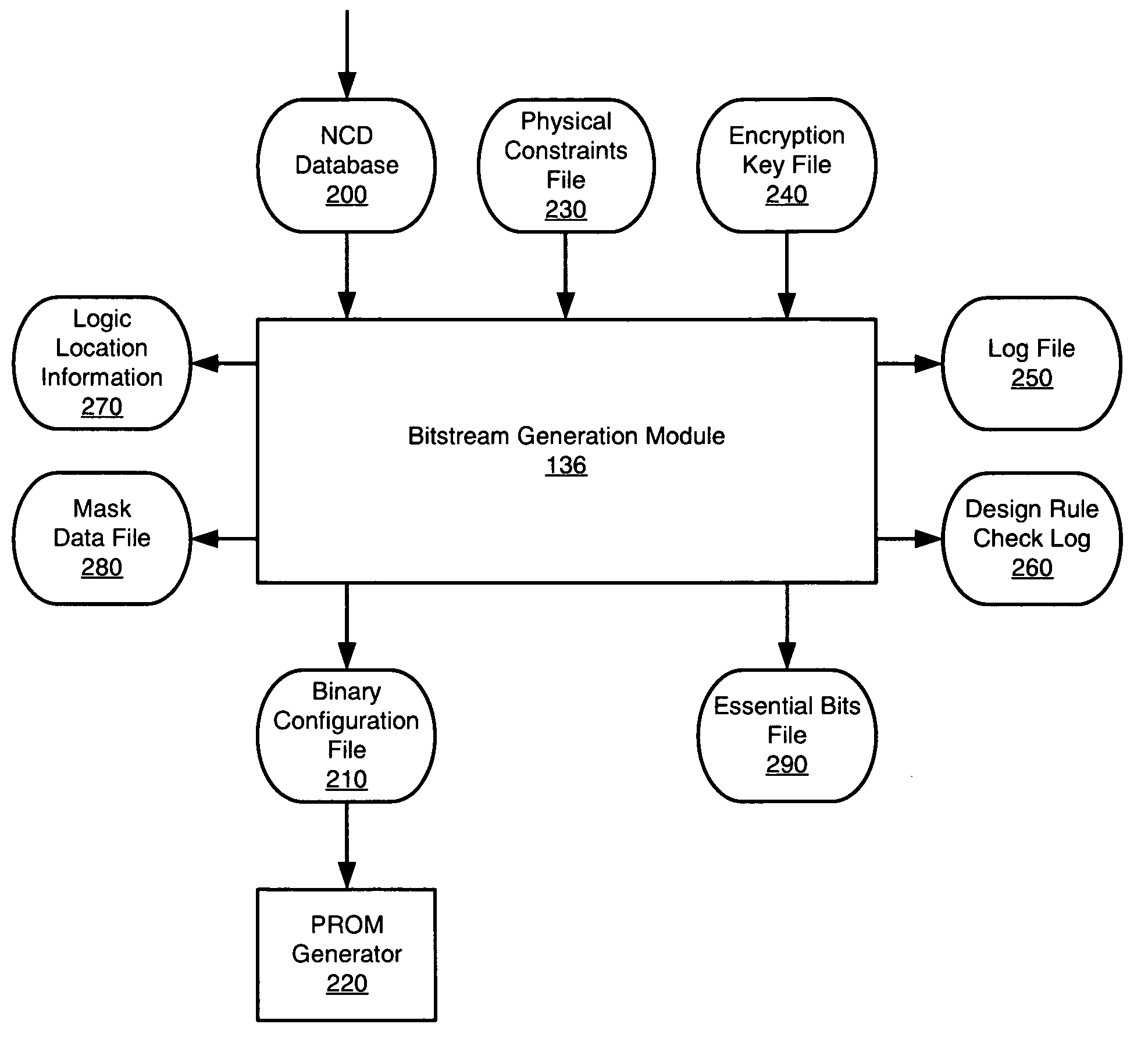
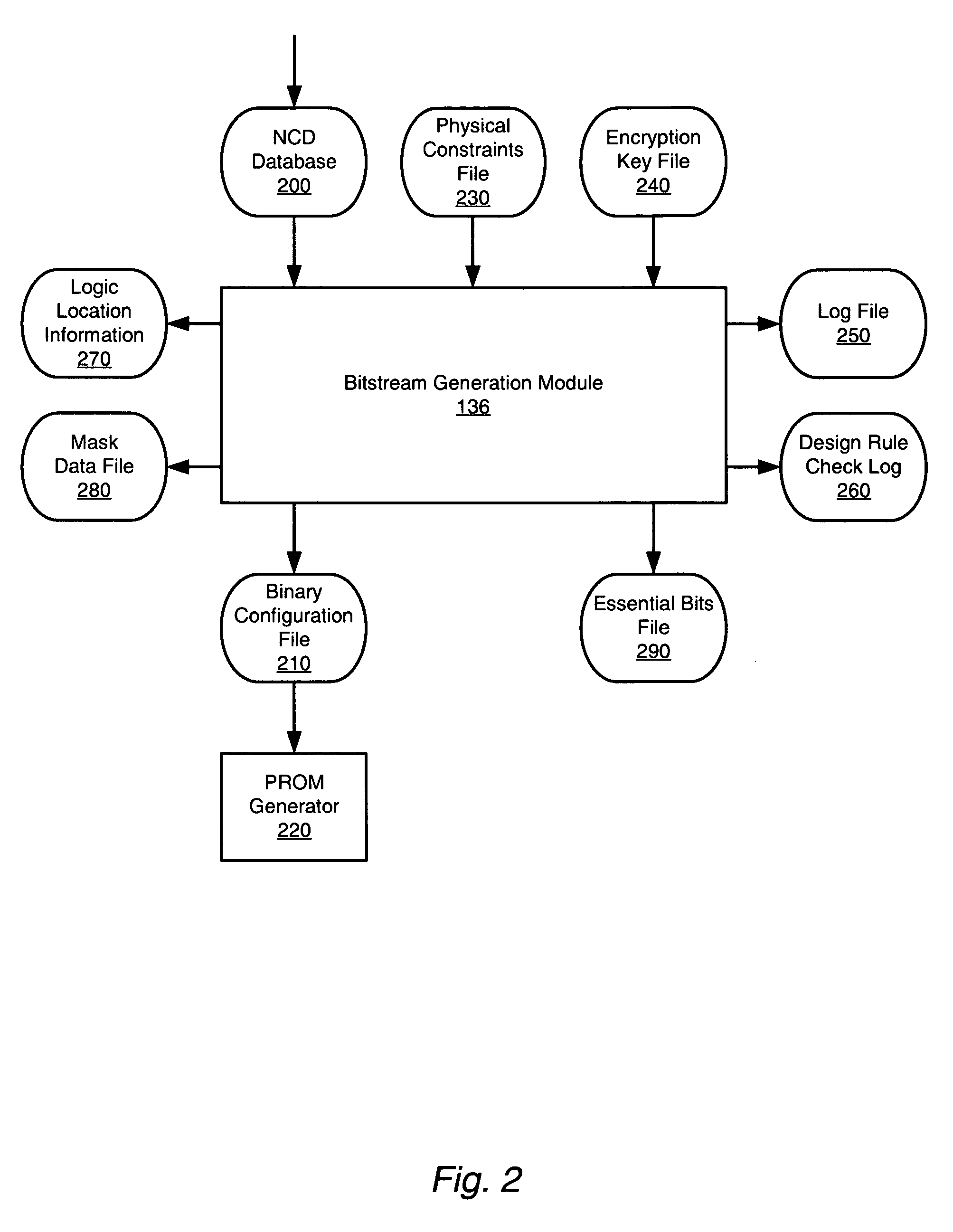
[0014]Embodiments of the present invention addresses the foregoing limitations by providing a method and system capable of generating a bitstream view of a programmable logic device (PLD) design. Embodiments of the present invention provides the ability to maintain information regarding the relationship between essential bits and logic elements. This information provides for the generation of a bitstream view when using a design environment of the present invention.

Problems solved by technology

As will be appreciated, essential configuration bits that retain their default value are therefore difficult to distinguish from unused configuration bits.
Often, however, a project will require the identification or count of the design's essential bits, and so present a fairly intractable problem.
However, these approached have suffered from a variety of infirmities.
For example, such a tool chain may be able identify a large portion of the essential bits of a design, but with limited accuracy, or may be able to identify only a small subset of the essential bits, albeit with acceptable accuracy.
Moreover, such approaches can require significant resources (e.g., requiring the grouping of configuration bits be performed manually, when attempting to coordinate configuration bits and logic elements).
Practical issues arise when using a tool chain such as that described above.
One limitation is that an assortment of environments and tools are required: stand-alone programs, scripts, database engines and other design environment tools.
Moreover, file sizes, memory requirements and execution times can be considerable for large designs when using such an approach.
In many cases, such a tool chain is also limited in the number of architectures that can be supported.
Although scripts can be used to automatically generate some of the requisite information from device model files, substantial manual work is still required for logic resources.
Such coverage can also be difficult to achieve and verify.
The effort involved is compounded by the large number of tile types in some architectures.
Although most of these options affect the startup process, they are sometimes used for other purposes, and so their effects may go unnoticed or undetected.

Method used


Image

  • Method and system for generating a bitstream view of a design
  • Method and system for generating a bitstream view of a design
  • Method and system for generating a bitstream view of a design

Examples


Embodiment Construction

[0028]The following is intended to provide a detailed description of an example of the invention and should not be taken to be limiting of the invention itself. Rather, any number of variations may fall within the scope of the invention which is defined in the claims following the description.

Introduction

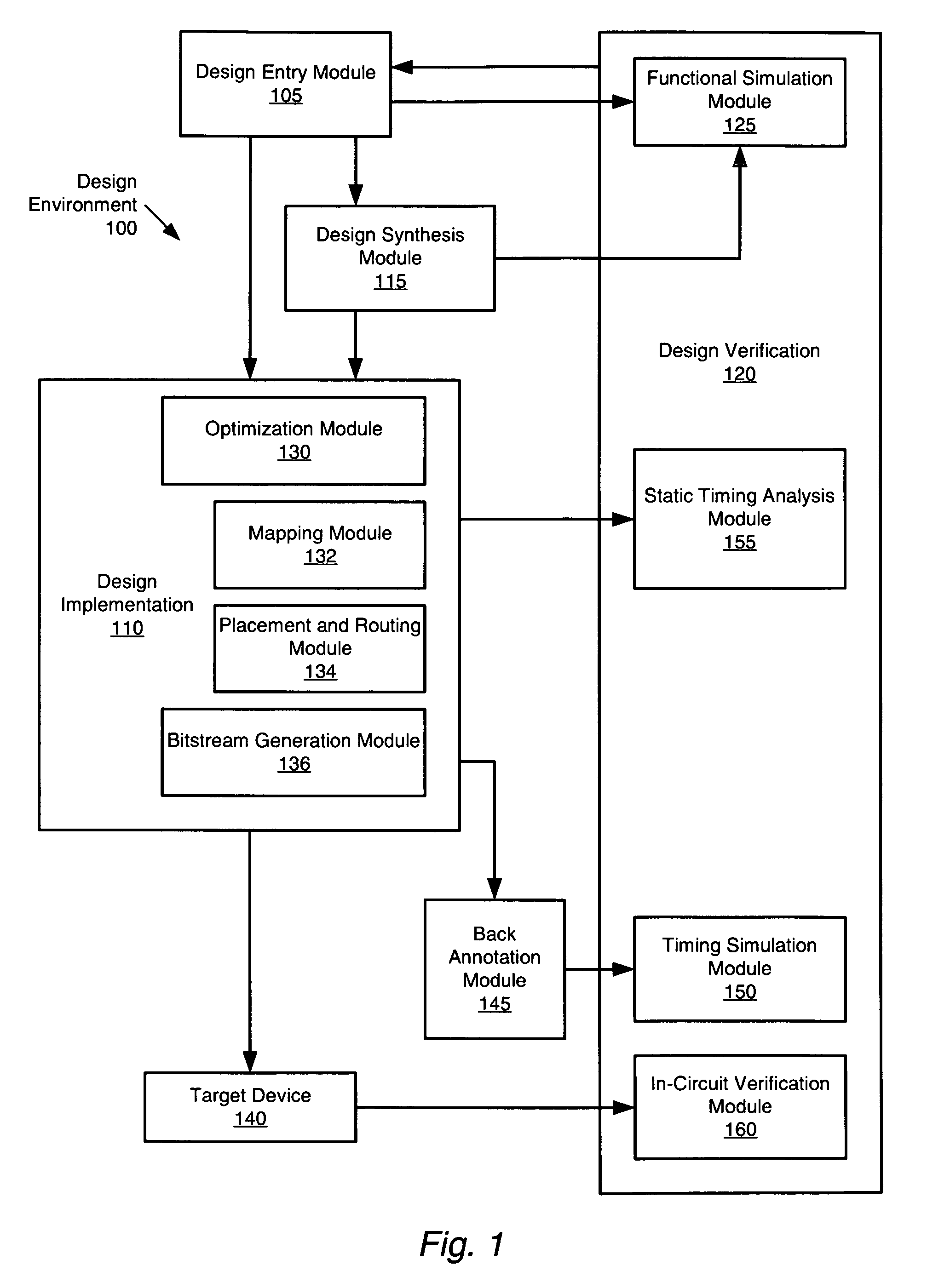
[0029]Embodiments of the present invention provides a method and system capable of generating a bitstream view of a programmable logic device (PLD) design. A design environment according to an embodiment of the present invention provides different views of a design, such as logical / physical, hierarchical / flat, and timing, and also provides a bitstream view.

[0030]The present invention can be implemented, for example, in a design environment's configuration bitstream generator. Using a tool thus modified, it is possible to support querying of information relating configuration bits to user-named design element instances (or more generically, logic elements). Thus, the correspondence b...


PUM


Abstract

A method and system for generating a bitstream view of a programmable logic device (PLD) design are disclosed. The present invention allows for the correlation of a physical circuit description (e.g., one or more of a PLD design's essential configuration bits) and a logical circuit description (e.g., one or more of the logic elements that make up a PLD design), which can also be viewed as correlating one or more of the physical elements of the design's implementation in the PLD with one or more of the design's logical elements.

Description

BACKGROUND OF THE INVENTION[0001]1. Field of the Invention[0002]This invention relates to the field of programmable logic devices, and more particularly relates to a method and system for identifying the essential configuration bits of a design.[0003]2. Description of the Related Art[0004]In creating a design that is to be programmed into a programmable logic device (PLD), a designer employs a program tasked with generating the configuration bits representing the design (referred to as a configuration bitstream generation module, or the like), among other such design tools. A configuration bitstream generation module determines the value of each configuration bit used in the design, based on a description of the circuit being implemented. Such a circuit description typically includes logic elements, logical connections and other such information.[0005]Typically, the set of configuration bits used by a given design is only a subset of the total number of configuration bits in the pro...

Claims


Application Information

Patent Timeline
IPC IPC(8): G06F17/50
CPCG06F17/5045G06F30/30
Inventor PATTERSON, CAMERON D.SUNDARARAJAN, PRASANNABLODGET, BRANDON J.MCMILLAN, SCOTT P.
Owner XILINX INC
Learn More