Progressive takeoff thrust ramp for an aircraft

a technology of propellers and ramps, applied in the field of aircraft, can solve the problems of vibration of the fan blades, the aerodynamics of the separation of air and the fan blades of the engine, and the affecting the maintenance schedule of the engin

Active Publication Date: 2013-12-24
THE BOEING CO
View PDF15 Cites 16 Cited by
  • Summary
  • Abstract
  • Description
  • Claims
  • Application Information

AI Technical Summary

Problems solved by technology

The amount of thrust generated by an engine may affect the maintenance schedule required for an engine.
This separation of air may provide poor aerodynamics with respect to fan blades within the engine.
If the engine is providing a high-level thrust, poor aerodynamics may cause vibrations on the fan blades.
These vibrations may result in requiring more frequent replacement or maintenance of the blades.
This type of increased maintenance increases cost and makes the aircraft unavailable more often.

Method used


Image

  • Progressive takeoff thrust ramp for an aircraft
  • Progressive takeoff thrust ramp for an aircraft
  • Progressive takeoff thrust ramp for an aircraft

Examples


Embodiment Construction

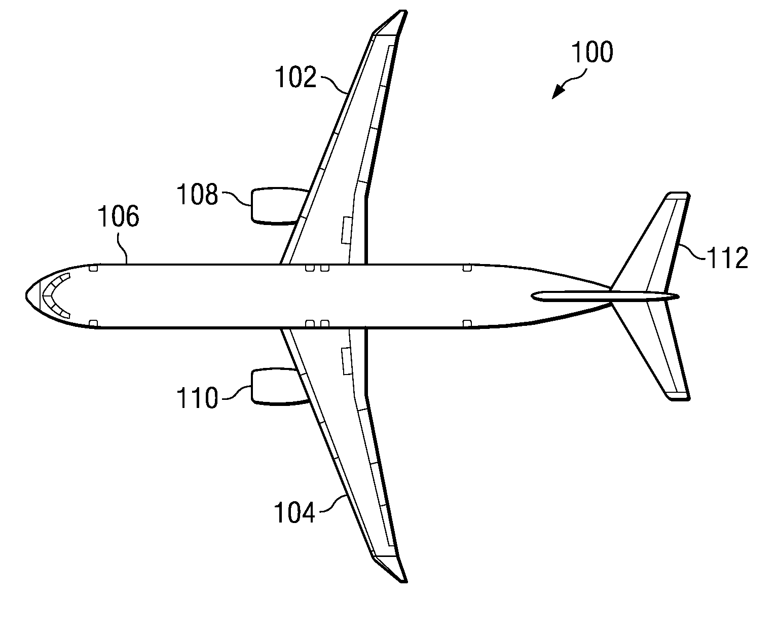
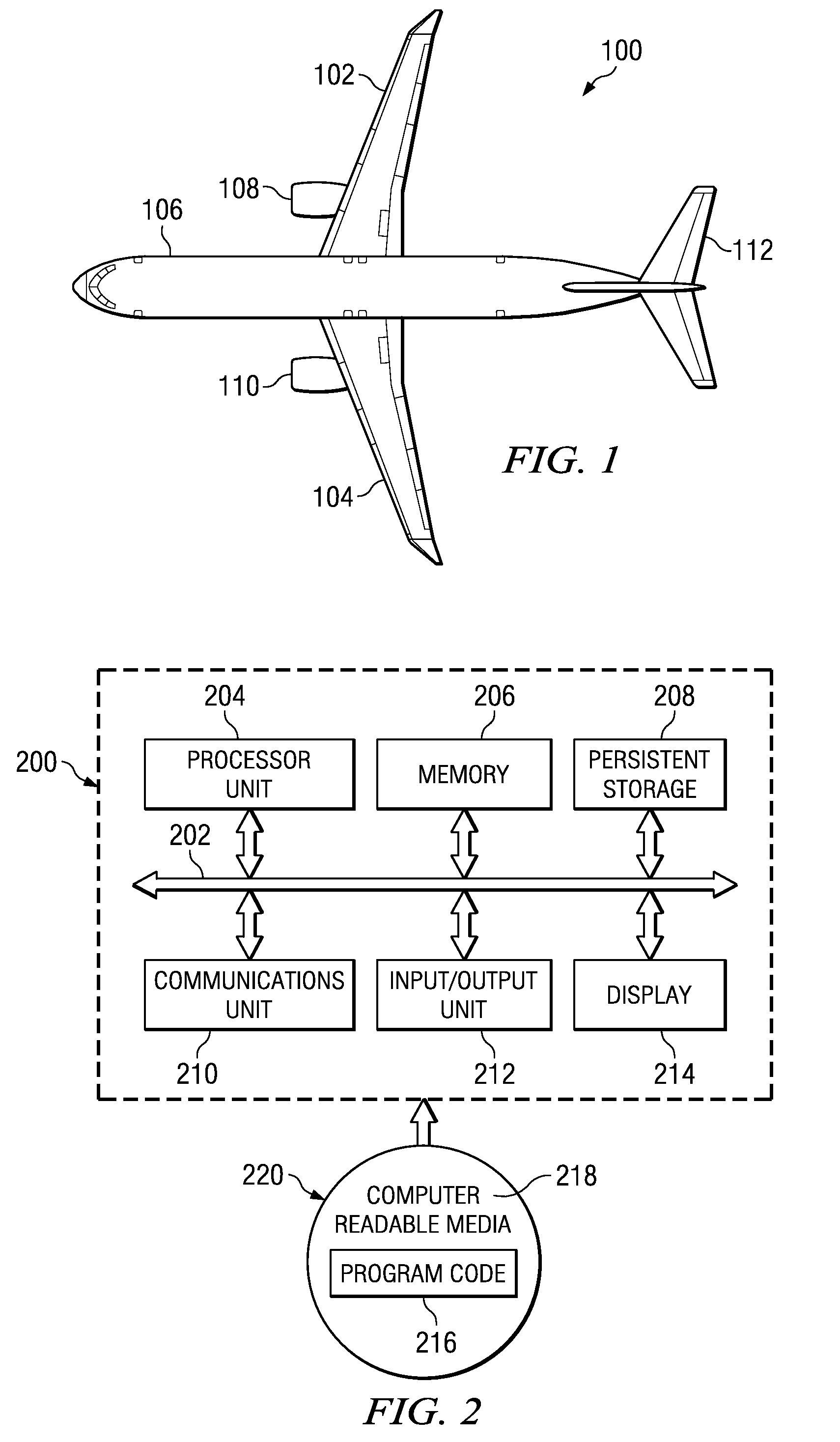
[0027]With reference now to the figures, and in particular, with reference to FIG. 1, a diagram of an aircraft is depicted in which an advantageous embodiment may be implemented. Aircraft 100 is an example of an aircraft in which a method and apparatus for controlling engine power may be implemented. In this illustrative example, aircraft 100 has wings 102 and 104 attached to body 106. Aircraft 100 includes wing mounted engine 108, wing mounted engine 110, and tail 112. In particular, the different advantageous embodiments may control a level of thrust that may be generated by wing mounted engine 108 and wing mounted engine 110 when aircraft 100 is on the ground.

[0028]Although a wing mounted twin engine aircraft is illustrated in FIG. 1, this illustration is provided for purposes of illustrating one type of aircraft in which different advantageous embodiments may be implemented. The different advantageous embodiments may be implemented on other types of aircraft with other numbers o...


PUM


Abstract

A method is presented for controlling thrust generated by aircraft engines. Engine thrust is controlled based on aircraft groundspeed and airspeed during the initial part of takeoff. Limiting thrust at low groundspeed during the initial phase of takeoff has significant benefits that reduce engine stress during this brief but critical phase leading to flight. Logical elements combine both groundspeed and airspeed in such a way that the operator perceives a smooth progressive thrust increase consistent with normal engine operation.

Description

BACKGROUND INFORMATION[0001]1. Field[0002]The present disclosure relates generally to aircraft and in particular to a method and apparatus for controlling the flight of an aircraft. Still more particularly, the present disclosure relates to a method, apparatus, and computer program product for controlling thrust generated by the engine of an aircraft.[0003]2. Background[0004]Takeoff is a phase of flight when an aircraft transitions from moving along the ground to flying in the air. An aircraft may make this transition when a takeoff speed is reached. The takeoff speed for an aircraft may vary based on a number of factors. These factors include, for example, air density, aircraft gross weight, aircraft configuration, and other suitable factors.[0005]The speed needed for a takeoff is relative to the motion of the air. For example, headwind reduces the amount of groundspeed at the point of takeoff. In contrast, a tailwind increases the groundspeed at the point of takeoff.[0006]The amou...

Claims


Application Information

Patent Timeline
Patent Type & Authority Patents(United States)
IPC IPC(8): G01C23/00
CPCF02C9/28
Inventor COUEY, LYLE M.PARSONS, KEITH D.
Owner THE BOEING CO
Why Eureka
Try Eureka