Chain tool

Inactive Publication Date: 2008-03-18
ZIPTY RACING
View PDF9 Cites 9 Cited by
  • Summary
  • Abstract
  • Description
  • Claims
  • Application Information

AI Technical Summary

Benefits of technology

[0006]The present invention provides a tool to make the task of master link insertion or removal simple and safe. The tool is also small, easy to handle, and relatively inexpensive. The tool includes a support member, a chain coupler, and a pry member. The chain coupler exte

Problems solved by technology

However, this can be a difficult operation as the screwdriver will often slip off of the end of the clip during the attempt or the clip will pop off with a spring loaded force that will cause it to become separated from the chain and potentially lost.
A slip of the screwdriver can also injure the person at

Method used


Image

  • Chain tool
  • Chain tool
  • Chain tool

Examples


Embodiment Construction

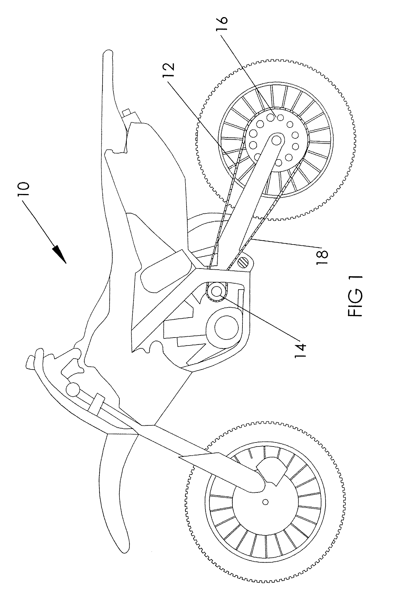
[0016]FIG. 1 illustrates an off-road motorcycle (vehicle 10) that includes a roller type chain 12 secured between a front sprocket 14 and a rear sprocket 16 to transfer the motive force from the counter shaft of the vehicle engine to the rear wheel. This illustrates a typical application of a roller type chain that includes a master link 18 securing the chain in an endless loop around the sprockets 14, 16. Before the chain can be removed from vehicle 10, master link 18 must be removed from chain 12 while chain 12 is on vehicle 10. Thus, the somewhat awkward operation of removing the master link with pliers or a screwdriver must be carried out in this environment.

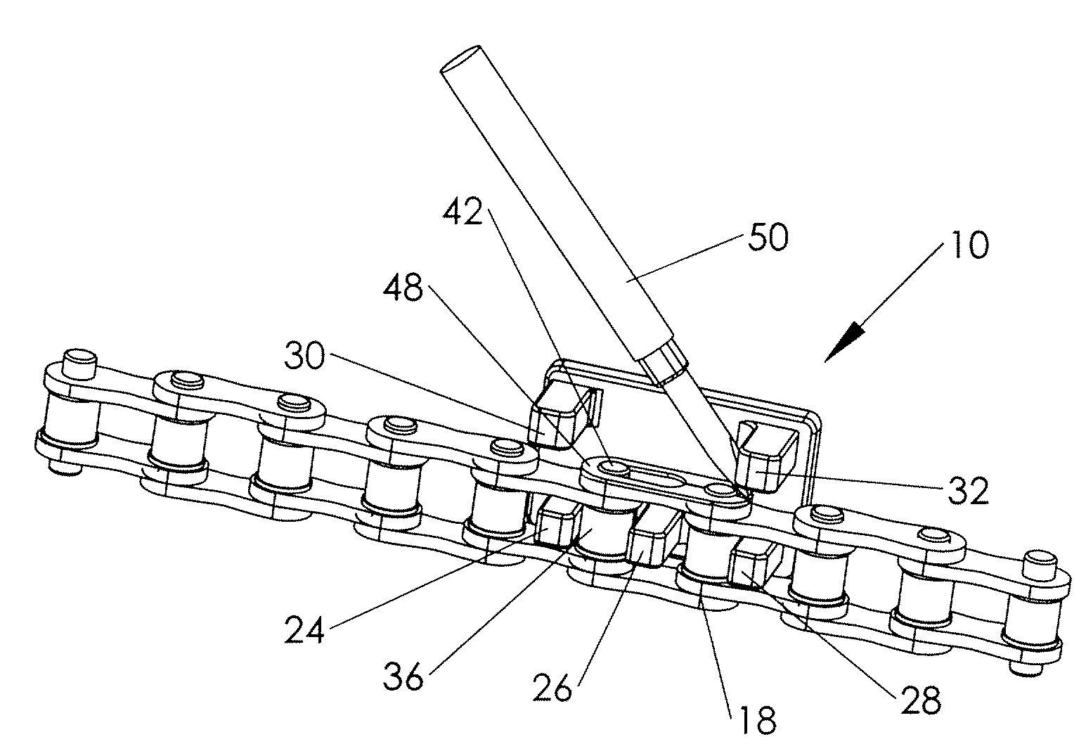
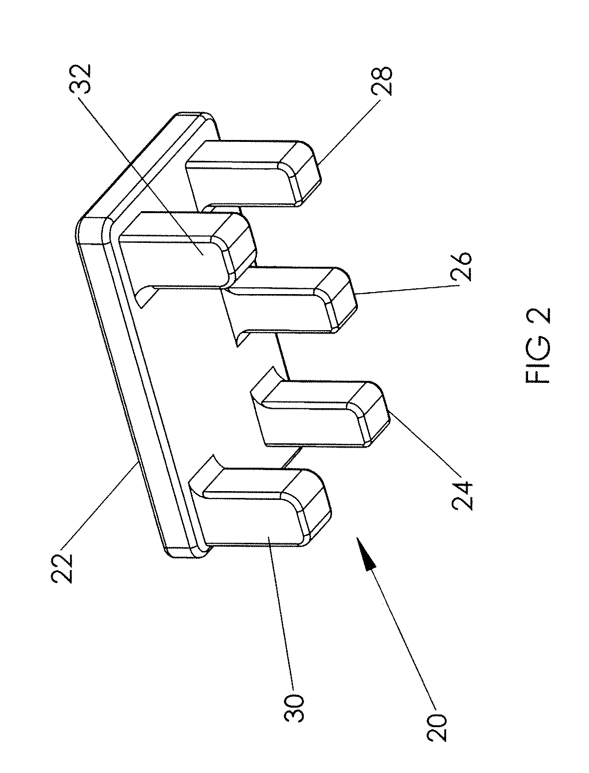
[0017]FIG. 2 illustrates a chain tool 20 to make the task of removing chain 12 much simpler. Chain tool 20 includes a top 22, a left leg 24, a middle leg 26, and a right leg 28 all used to secure chain tool 20 to chain 12 as will be discussed in more detail below. A left post 30 and right post 32 also project downwardly from...


PUM

PropertyMeasurementUnit
Lengthaaaaaaaaaa

Abstract

A tool for aiding master link removal from a chain. The master link includes two pins and a clip with two ends extending from one pin to the other. The chain includes plates, pins, and rollers. The chain has a longitudinal direction along the length of the chain. The tool includes a support member, a plurality of coupler legs, and two pry posts. The coupler legs extend from the support member and are sized to fit between adjacent chain rollers. The legs, combined with the support member, bridge across the master link to hold it secure relative to the pry posts. The pry posts extend from the support member laterally offset from the coupler legs. The pry posts are generally laterally adjacent the ends of the clip when the coupler legs are secured to the chain.

Description

FIELD OF THE INVENTION[0001]This invention relates generally to mechanic's tools and, more specifically, to a tool for use with a roller type chain.BACKGROUND OF THE INVENTION[0002]Roller type chains are used in various motorized and non-motorized mechanical applications for transmitting power from one shaft to another via sprockets and the roller type chain. Such chains may be used on stationary mechanical equipment or in vehicles such as automobiles, bicycles, and motorcycles. In many common applications the chain is removable from the sprockets to which it is attached by removal of a master link. The master link includes side plates and pins coupled with a clip to hold the side plates in place on the pins. The pins are secured through opposing chain links to close a chain a chain and complete the connection of the chain to a plurality of sprockets on which it moves. The master link is removed by popping the clip off of the master link pins, which include recesses in the ends ther...

Claims


Application Information

Patent Timeline
IPC IPC(8): B21L21/00
CPCB21L21/00
Inventor CUNDARI, DARYL
Owner ZIPTY RACING
Why Eureka
Try Eureka