Diagnosing a loss of refrigerant charge in a refrigerant system

a technology of refrigerant system and refrigerant charge, which is applied in the field of refrigerant system loss, can solve the problems of system loss of refrigerant charge, interruption of customer service, loss of cooling capacity,

Inactive Publication Date: 2008-03-18
CARRIER CORP
View PDF11 Cites 43 Cited by
  • Summary
  • Abstract
  • Description
  • Claims
  • Application Information

AI Technical Summary

Problems solved by technology

It is possible for the system to lose refrigerant charge through damaged components or loose connections or to be inadequately charged at the factory or in the field.
If an inadequate amount of charge is not detected early enough, it leads to the loss of cooling capacity and may cause an interruption in service to the customer.
Additionally, system components such as the compressor may malfunction or be damaged if there is an insufficient amount of refrigerant within the system.
Differentiating between such system malfunction modes and an inadequate amount of refrigerant charge using known techniques requires exhaustive troubleshooting.
Moreover, prior approaches do not provide low refrigerant charge amount information early enough to avoid possible component damage.

Method used


Image

  • Diagnosing a loss of refrigerant charge in a refrigerant system
  • Diagnosing a loss of refrigerant charge in a refrigerant system

Examples


Embodiment Construction

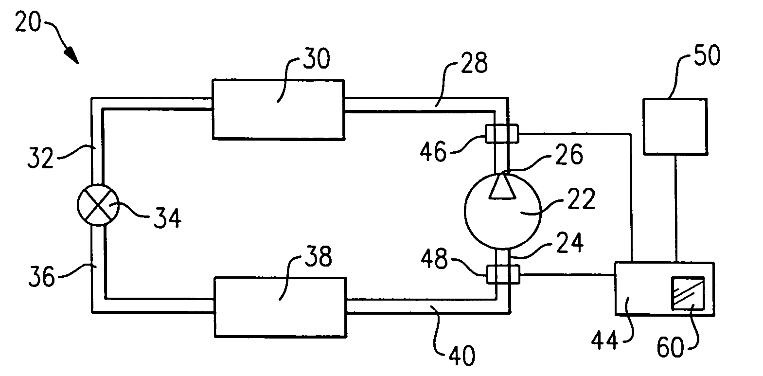
[0015]FIG. 1 schematically shows a cooling circuit 20 that is part of an air conditioning system, for example. A compressor 22 draws refrigerant through a suction port 24 and provides a compressed refrigerant under pressure to a compressor discharge port 26. The high temperature, pressurized refrigerant flows through a conduit 28 to a condenser 30 where the refrigerant gas rejects heat and usually condenses into a liquid as known. The liquid refrigerant flows through a conduit 32 to an expansion device 34.

[0016]In one example, the expansion device 34 is a valve that operates in a known matter to allow the liquid refrigerant to partially evaporate and flow into a conduit 36 in the form of a cold, low pressure refrigerant. This refrigerant flows through an evaporator 38 where the refrigerant absorbs heat from air that flows across the evaporator coils, which provides cool air to the desired space as known. Refrigerant exiting the evaporator 38 flows through a conduit 40 to the suction...


PUM

PropertyMeasurementUnit
temperaturesaaaaaaaaaa
temperatureaaaaaaaaaa

Abstract

A refrigerant system has a controller associated with it that determines an equilibrium pressure when the system is inactive. The controller determines if the equilibrium pressure differs from an expected equilibrium pressure corresponding to a current ambient temperature and the selected refrigerant type. When the difference exceeds a selected threshold, the controller determines that the amount of refrigerant within the circuit is below a desired level. In one example, the controller provides an indication of a low charge amount. The disclosed technique allows early detection of refrigerant charge loss and differentiation between loss-of-charge and other failure modes. Consequently, system performance is enhanced, component damage is prevented, service interruptions and maintenance are reduced, exhaustive troubleshooting is avoided and potential exposure to refrigerant substances is minimized.

Description

BACKGROUND OF THE INVENTION[0001]This invention generally relates to refrigerant systems. More particularly, this invention relates to determining an amount of refrigerant charge within such systems.[0002]These systems typically are charged at a factory or in the field after installation with an amount of refrigerant to provide adequate system performance for expected operating conditions.[0003]It is possible for the system to lose refrigerant charge through damaged components or loose connections or to be inadequately charged at the factory or in the field. It is necessary to determine refrigerant charge loss to avoid interruptions in service for the customers and prevent a failure of the system components, such as a compressor.[0004]Low refrigerant charge conditions typically do not become apparent until high demand conditions, at high ambient temperatures for example, when full load operation is required to provide the desired amount of cooling. If an inadequate amount of charge ...

Claims


Application Information

Patent Timeline
Patent Type & Authority Patents(United States)
IPC IPC(8): G01K13/00F25B45/00F25B49/00
CPCF25B49/005F25B2700/1931F25B2700/1933F25B2700/2106
Inventor LIFSON, ALEXANDERTARAS, MICHAEL F.
Owner CARRIER CORP
Why Eureka
Try Eureka