
Nonvolatile storage device and control method thereof

a storage device and non-volatile technology, applied in the direction of static storage, digital storage, instruments, etc., can solve the problems of loss of written electric charge, charge loss phenomenon, and exhausted read margin of these memory cells with respect to the reference cell, so as to reduce the time required for program operation

Active Publication Date: 2008-06-19
INFINEON TECH LLC
View PDF4 Cites 22 Cited by
  • Summary
  • Abstract
  • Description
  • Claims
  • Application Information

AI Technical Summary

Benefits of technology

[0009]The present invention has been made to overcome the above drawbacks of the prior art and provide a nonvolatile storage device and a control method thereof that responds to a decrease in electric charge stored in memory cells attributed to the charge loss phenomenon occurring during program operation by adjusting the level of a program verify operation according to the degree of the charge loss so that the program operation can be performed with little (if any) interruption.
[0011]In an embodiment with the above arrangement, if electric charge is lost owing to the charge loss phenomenon in the memory cells, the degree of the charge loss can be detected by detecting the threshold voltage of the dynamic reference cell in the program operation. According to the amount of electric charge lost by the charge loss phenomenon, the verify voltage of a subsequent program operation is adjusted, thereby controlling the amount of electric charge stored in the target memory cell of the program operation. This eliminates the need for the performance of a refresh operation on the memory cells and the charged dynamic reference cell to compensate for the lost electric charge, so that the time required for the program operation can be reduced.
[0013]In an embodiment with the above arrangement, if the electric charge stored in the memory cells are lost by the charge loss phenomenon, the reference current can be changed within the reference cell according to the degree of the charge loss. In accordance with the amount of electric charge lost by the occurrence of the charge loss phenomenon, the verify voltage of a subsequent program operation and the amount of electric charge trapped in the target memory cell of the program operation are adjusted. Therefore, there would be no need to perform a refresh operation to compensate for the electric charge lost in the memory cells and the dynamic cell, so that the time required for the program operation can be reduced.
[0014]According to embodiments of this invention, if charge loss phenomenon occurs in areas of charge storage, the threshold voltage of the program verify operation is adjusted according to the threshold voltage of the dynamic reference cell which has lost electric charge, so that a refresh operation, which has heretofore been needed to compensate for the loss caused by the charge loss phenomenon, is no longer necessary and a program operation that provides proper read margins can be performed within a short time irrespective of the presence / absence of the charge loss phenomenon.

Problems solved by technology

However, in the memory cells disclosed above, if the number of rewriting operations increases, the charge loss phenomenon, (i.e., a loss of written electric charge) will occur.
However, this leads to an unfavorable situation that occurs when a target memory cell is programmed and its corresponding reference cell is also programmed to ensure a read margin, while the charge loss phenomenon occurs in other memory cells which share the reference cell with the target memory cell, so that the read margin of these memory cells with respect to the reference cell will be exhausted.
This presents a problem as the program operation can take a lot of time.
Therefore, if a bias is applied to these memory cells at the same time, the memory cells which are the targets of the refresh operation may be brought into an excessively programmed state.
This, however, brings about an undesirable result in that the program operation performed simultaneously with the refresh operation can take a long time.

Method used


Image

  • Nonvolatile storage device and control method thereof
  • Nonvolatile storage device and control method thereof
  • Nonvolatile storage device and control method thereof

Examples


first embodiment

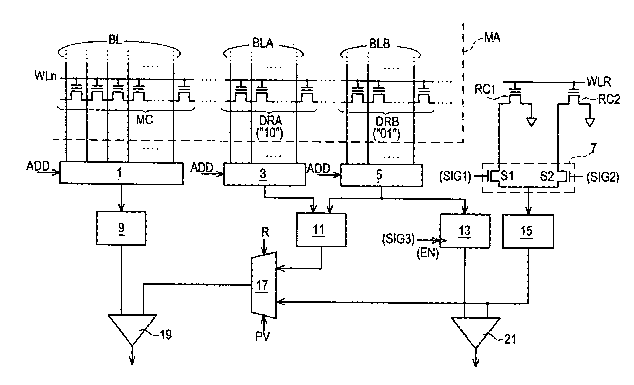
[0037]FIG. 3 shows a circuit block diagram associated with a Specifically, FIG. 3 shows the configuration of a circuit in which the verify voltage is decreased in the next program operation to be performed if a drop in the threshold voltage of the dynamic reference cell DRB (“01”) is checked. This is a circuit portion associated with the verify operation and the read operation performed during a program operation. The memory cells MC and the dynamic reference cells DRA, DRB, which are arranged in the memory cell array MA, are coupled to a common word line WLn. They are also coupled to Y decoders 1, 35 through a bit line BL and bit lines BLA, BLB, respectively.

[0038]In response to an address signal ADD, the Y decoders 1, 3, 5 select a memory cell MC that is a target of a reading operation, and the dynamic reference cells DRA and DRB corresponding to this memory cell MC and couples them to cascode circuits 9, 11, 13 respectively.

[0039]The cascode circuits 9, 11, 13 apply a specified ...

second embodiment

[0060]In the second embodiment, the average value of the reference cell RC3 and the dynamic reference cell DRB is used as the program verify voltage. It is therefore convenient to make the threshold voltage of the reference cell RC3 equal to the normal program verify voltage. If the charge loss phenomenon does not occur in the memory cells MC etc. within the memory cell array, the verify voltage for the normal program operation is set as the average verify voltage. If the charge loss phenomenon occurs, the verify voltage is shifted from the normal program verify voltage to a lower value.

[0061]Herein, the reference cell RC3 serves as one example of the third reference cell. The dynamic reference cells DRA (“10”) and DRB (“01”) serve as examples of the first and second dynamic cells, respectively. The cascode circuit 11 serves as one example of the averaging circuit, and the Y decoder 3, the switch device 3 and the AND circuit A1 constitute a section that is one example of the switchi...


PUM


Abstract

A nonvolatile memory device that responds to a decrease in electric charge stored in memory cells attributed to the charge loss phenomenon occurring during program operation by adjusting the level of a program verify operation according to the degree of the charge loss so that the program operation can be performed with little (if any) interruption.

Description

CROSS-REFERENCES TO RELATED APPLICATIONS[0001]This is a continuation in part of International Application No. PCT / JP2006 / 340280, filed Dec. 18, 2006 which was not published in English under PCT Article 21(2).TECHNICAL FIELD[0002]The invention relates to a nonvolatile storage device which uses dynamic reference cells for reading data from memory cells provided with a charge storage layer and a control method thereof. More particularly, the invention relates to the technique of reducing programming time and increasing the accuracy of the data readout.BACKGROUND ART[0003]In nonvolatile memory cells that retain electric charges to store data in their charge storage layers, repetitive rewriting sometimes causes “a charge loss phenomenon” in which the retained electric charge decreases. The nonvolatile semiconductor storage device disclosed in International Publication No. 2004-097839 Gazette is configured to store 2-bit data in every memory cell by retaining an electric charge in a trap ...

Claims


Application Information

Patent Timeline
Patent Type & Authority Applications(United States)
IPC IPC(8): G11C16/04
CPCG11C16/28G11C16/3459G11C16/3454
Inventor YAMASHITA, MINORU
Owner INFINEON TECH LLC
Learn More