
Seed placement system for use in a seeding machine

a seeding machine and seed placement technology, applied in the field of seeding machines, can solve the problems of limiting the compactness (i.e., the reduction of the overall size) of the seed metering system, and the complexity of the mechanism necessary to properly meter the seeds, so as to achieve simple and effective definition and accelerate the seeding

Active Publication Date: 2008-03-18
DEERE & CO
View PDF43 Cites 62 Cited by
  • Summary
  • Abstract
  • Description
  • Claims
  • Application Information

AI Technical Summary

Benefits of technology

[0011]An advantage of the present invention is that the wheel meters and accelerates the seeds in a positive manner.
[0012]Another advantage is that the bristles at the circumferential periphery of the wheel positively engage the seeds and carry the seeds past the seed slide, regardless of the size and orientation of the seeds.
[0013]Yet another advantage is that the gripping outside layer at the circumferential periphery of the wheel may take the form of several different materials having a high coefficient of friction, such as bristles, a foam pad, an expanded foam pad, a mesh pad, a fiber pad and a grit layer.
[0014]A further advantage is that the housing partially surrounding the wheel for directing the seeds past the wheel is simply and effectively defined by the seed slide and a pair of side plates.
[0015]A still further advantage is that the deflector may intermittently deflect the gripping outside layer of the wheel to ensure positive engagement with the seeds.

Problems solved by technology

On the other hand, the mechanisms necessary to properly meter the seeds, dispense the seeds at a predetermined rate and place the seeds at predetermined relative locations within the seed trench are relatively complicated.
The concentrically positioned driven shaft and sprockets may limit the compactness (i.e., reduction in overall size) of the seed metering system.

Method used


Image

  • Seed placement system for use in a seeding machine
  • Seed placement system for use in a seeding machine
  • Seed placement system for use in a seeding machine

Examples


Embodiment Construction

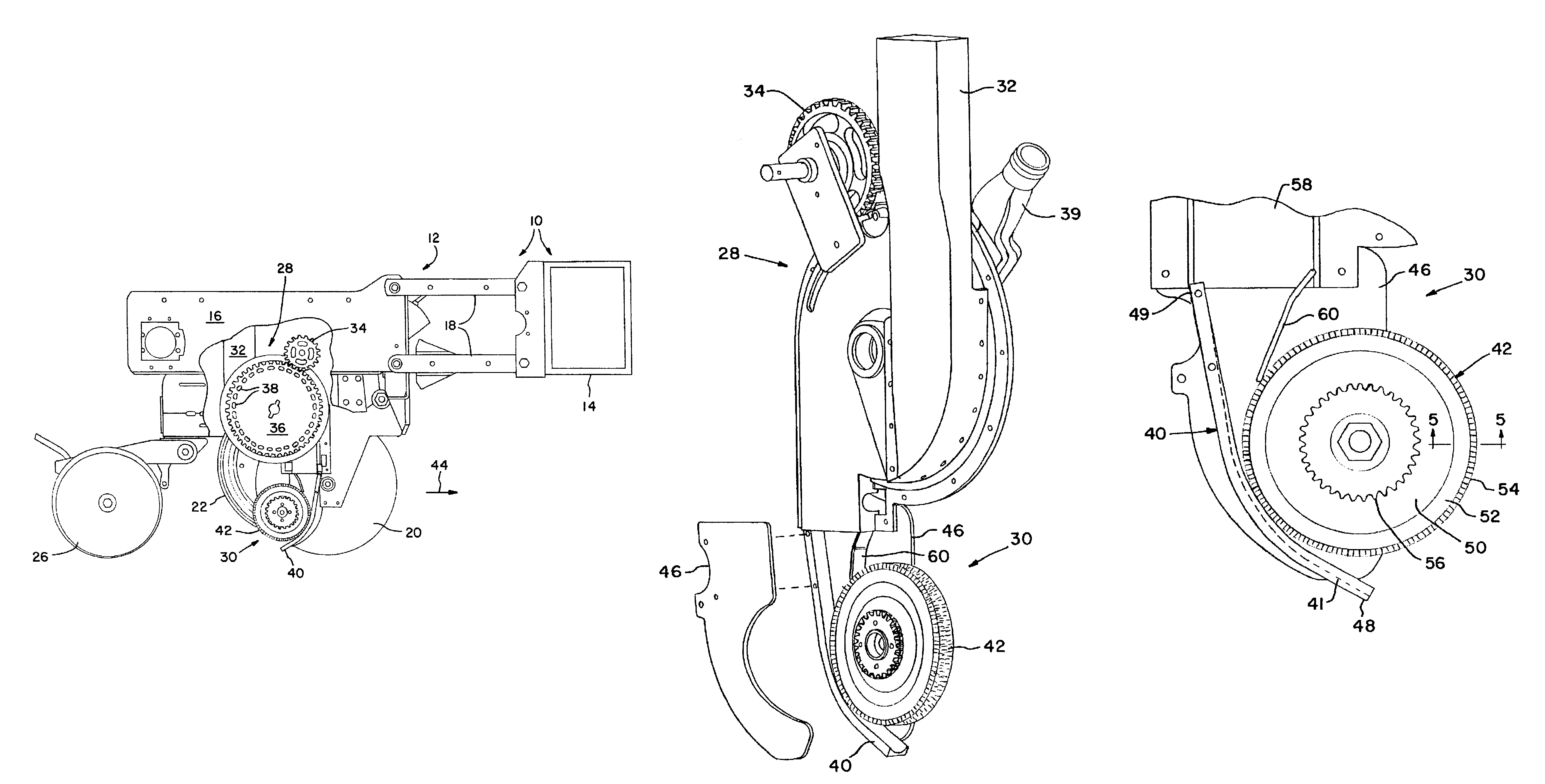
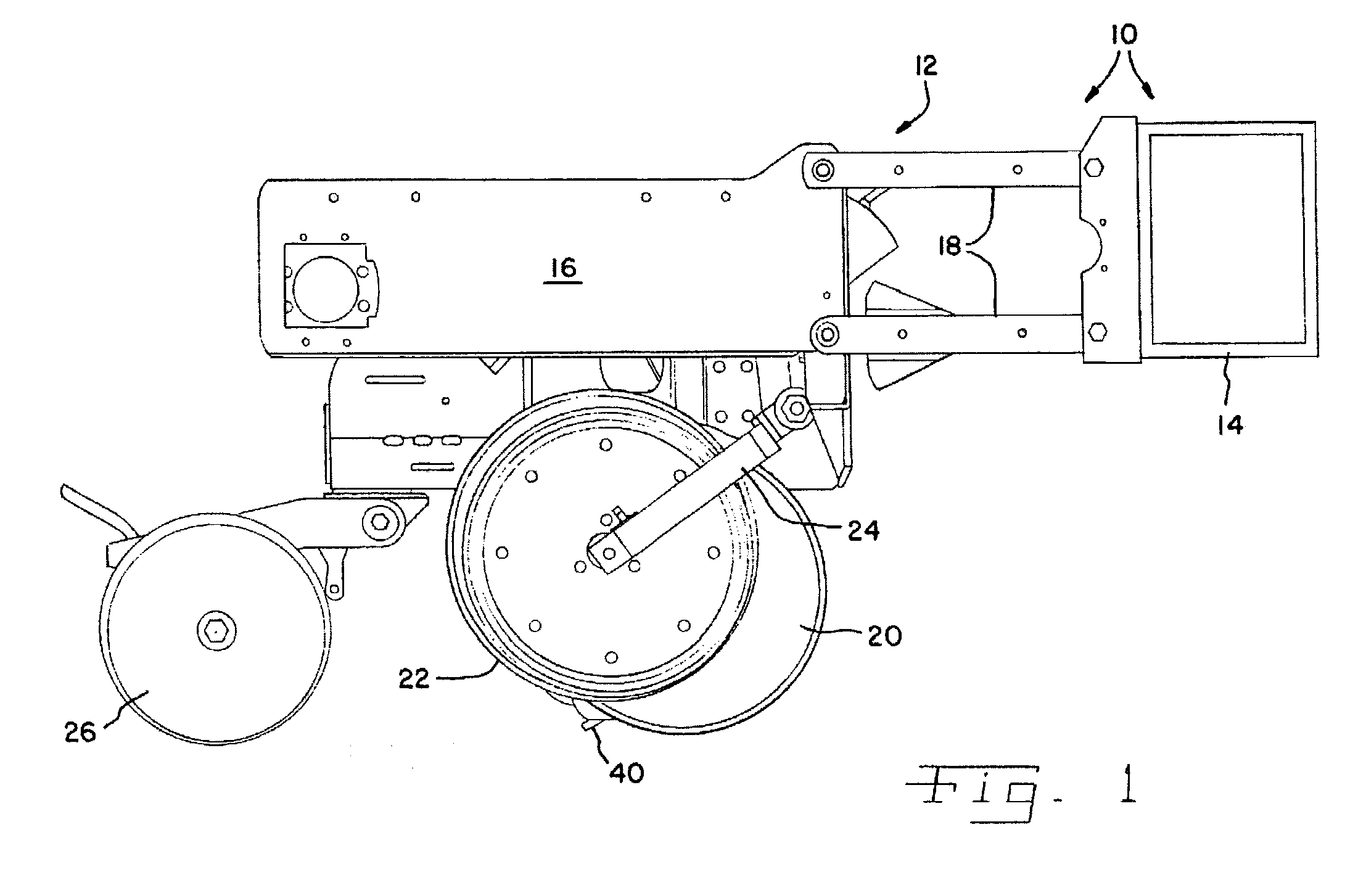
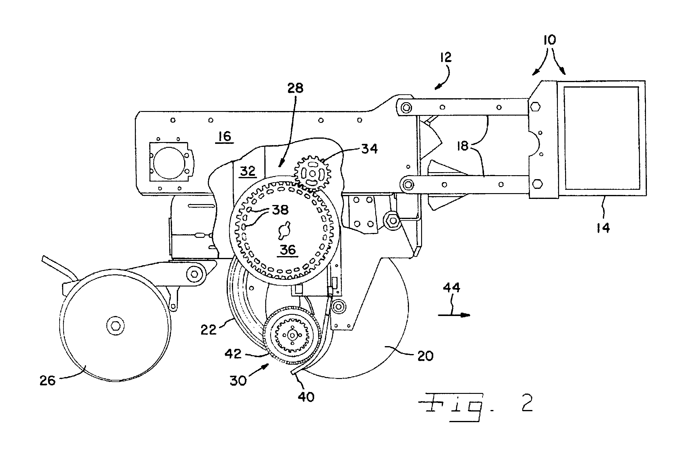
[0021]Referring now to the drawings, and more particularly to FIGS. 1 and 2, there is shown an embodiment of a seeding machine 10 of the present invention. In the embodiment shown, seeding machine 10 is in the form of a row crop planter but may also be in the form of a grain drill, etc. FIGS. 1 and 2 illustrate a single row crop unit 12 of a multi-row planter, with each row crop unit 12 being substantially identical and connected to a common tool bar 14. Only a single row crop unit 12 is shown for simplicity sake.

[0022]Row crop unit 12 includes a multi-part frame 16 which is attached to tool bar 14 by parallel linkage 18. Tool bar 14 is coupled to a traction unit (not shown), such as an agricultural tractor. For example, tool bar 14 may be coupled to an agricultural tractor using a 3-point hitch assembly. Tool bar 14 may be coupled with transport wheel assemblies, marker arms, etc. which may be of conventional design and not shown for simplicity sake. The transport wheels, in known ...


PUM


Abstract

A seeding machine includes at least one seed metering system and at least one seed placement system. Each seed placement system is in communication with a corresponding seed metering system. Each seed placement system includes a housing having a seed slide, and a wheel at least partly disposed within the housing. The wheel has a circumferential periphery with a plurality of contiguous disc joint surfaces. The periphery is positioned adjacent to at least part of the seed slide. The invention comprises, in another form thereof, a method of placing seeds with a seeding machine in a trench formed in soil. Seeds are received at a predetermined rate at a seed placement system. The seed placement system includes a seed slide, and a wheel having a conferential periphery position closely adjacent to at least part of the seed slide. The seeds are engaged at the predetermined rate against the wheel periphery. The seeds are carried past a closely adjacent area of the seed slide using the wheel periphery. The seeds are released from the wheel periphery.

Description

FIELD OF THE INVENTION[0001]The present invention relates to agricultural seeding machines, and, more particularly, to seed placement systems used to place seeds along a desired path and at a desired spacing within a seed trench.BACKGROUND OF THE INVENTION[0002]An agricultural seeding machine such as a row crop planter or grain drill places seeds at a desired depth within a plurality of parallel seed trenches formed in soil. In the case of a row crop planter, a plurality of row crop units are typically ground driven using wheels, shafts, sprockets, transfer cases, chains and the like. Each row crop unit has a frame which is moveably coupled with a tool bar. The frame may carry a main seed hopper, herbicide hopper and insecticide hopper. If a granular herbicide and insecticide are used, the metering mechanisms associated with dispensing the granular product into the seed trench are relatively simple. On the other hand, the mechanisms necessary to properly meter the seeds, dispense th...

Claims


Application Information

Patent Timeline
IPC IPC(8): A01C7/00A01C9/00A01C7/16A01C7/20
CPCA01C7/16A01C7/20
Inventor STEPHENS, LYLE E.KEATON, MILES R.ROMAN, ROBERT J.VALDEZ, JOSE M.
Owner DEERE & CO
Learn More