Drying device and drying method

a drying device and drying method technology, applied in the direction of drying machines with progressive movements, photosensitive materials, furnaces, etc., can solve the problems of deteriorating production efficiency, insatiable heating efficiency, and fogged photosensitive layer on the photosensitive planographic printing plate, so as to achieve the effect of preventing the fogged photosensitive layer and achieving heating efficiency

Inactive Publication Date: 2008-03-18
FUJIFILM HLDG CORP +1
View PDF11 Cites 5 Cited by
  • Summary
  • Abstract
  • Description
  • Claims
  • Application Information

AI Technical Summary

Benefits of technology

[0012]Taking the above problems into consideration, an object of the present invention is to provide a drying device and a drying method that use infrared rays, have satisfactory heating efficiency, and prevent fogging on a photosensitive layer.
[0014]According to the first aspect, the filter that blocks a predetermined range of wavelength is arranged between the infrared emitting device and a belt-shaped body. The infrared rays have a wavelength range of about 0.76 μm to 1 mm, and the wavelength range is divided into a near-infrared range (0.76 to 2 μm), a mid-infrared range (2 to 4 μm), and a far-infrared range (4 μm to 1 mm). As the wavelength range becomes shorter, the heating efficiency improves.
[0016]According to the first aspect, the use of the filter that blocks a predetermined range of wavelength can, for example, block a wavelength in a range of 1 μm or less from an infrared emitting device having a wavelength range of 2 μm or less. As a result, fogging on the photosensitive layer can be prevented, and high heating efficiency due to the low-wavelength range can be obtained.
[0017]In a second aspect of the invention, the wavelength in a range of 1 μm or less is blocked by the filter. According to the second aspect, when the wavelength in a range of 1 μm or less is blocked by the filter, the heating efficiency can be improved within a range where fogging does not occur on the photosensitive layer.
[0019]In this aspect, wavelengths of 1 μm or less are blocked by 30% or more. That is to say, the blocking ratio for wavelengths of 1 μm or less is specified, thereby further or more reliably improving the heating efficiency within the range where fogging does not occur on the photosensitive layer.
[0023]In the sixth aspect, the drying device, in which the filter that blocks a predetermined range of wavelength is arranged between the photosensitive planographic printing plate conveyed through the drying device and the infrared emitting device, dries the photosensitive layer on the photosensitive planographic printing plate. Accordingly, fogging on the photosensitive layer can be prevented, and heating efficiency can be achieved due to a low-wavelength range.

Problems solved by technology

When the photosensitive layer on the photosensitive planographic printing plate is dried, if the photosensitive planographic printing plate is heated in the low-wavelength range (near-infrared range) in which the heating efficiency is satisfactory, the photosensitive layer on the photosensitive planographic printing plate becomes fogged.
On the other hand, if the photosensitive planographic printing plate is heated in the high-wavelength range (far-infrared range), the heating efficiency is not satisfactory, and production efficiency deteriorates.

Method used


Image

  • Drying device and drying method
  • Drying device and drying method
  • Drying device and drying method

Examples


example

[0056]The surface of the web 12, which is a belt-shaped aluminum plate, is subject to a mechanical surface roughening process, a chemical etching process, an electrolytic surface roughening process, and an anodizing process. As a result, a substrate whose average surface roughness Ra is 0.48 μm is prepared. A positive planographic printing plate coating liquid is applied to the web 12 and is dried.

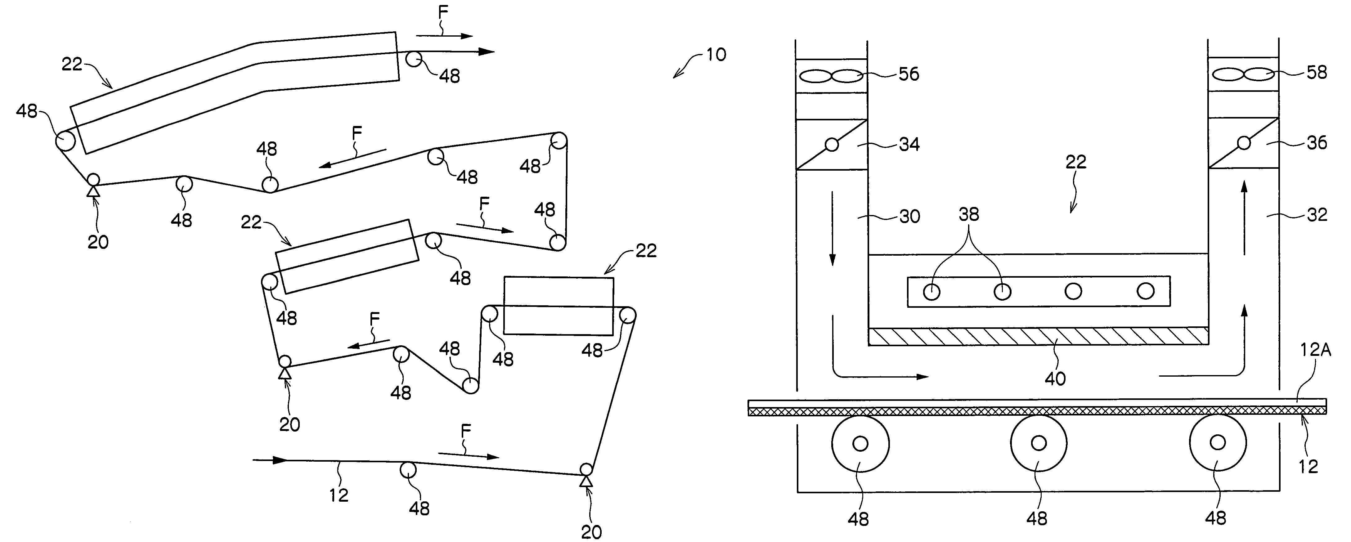
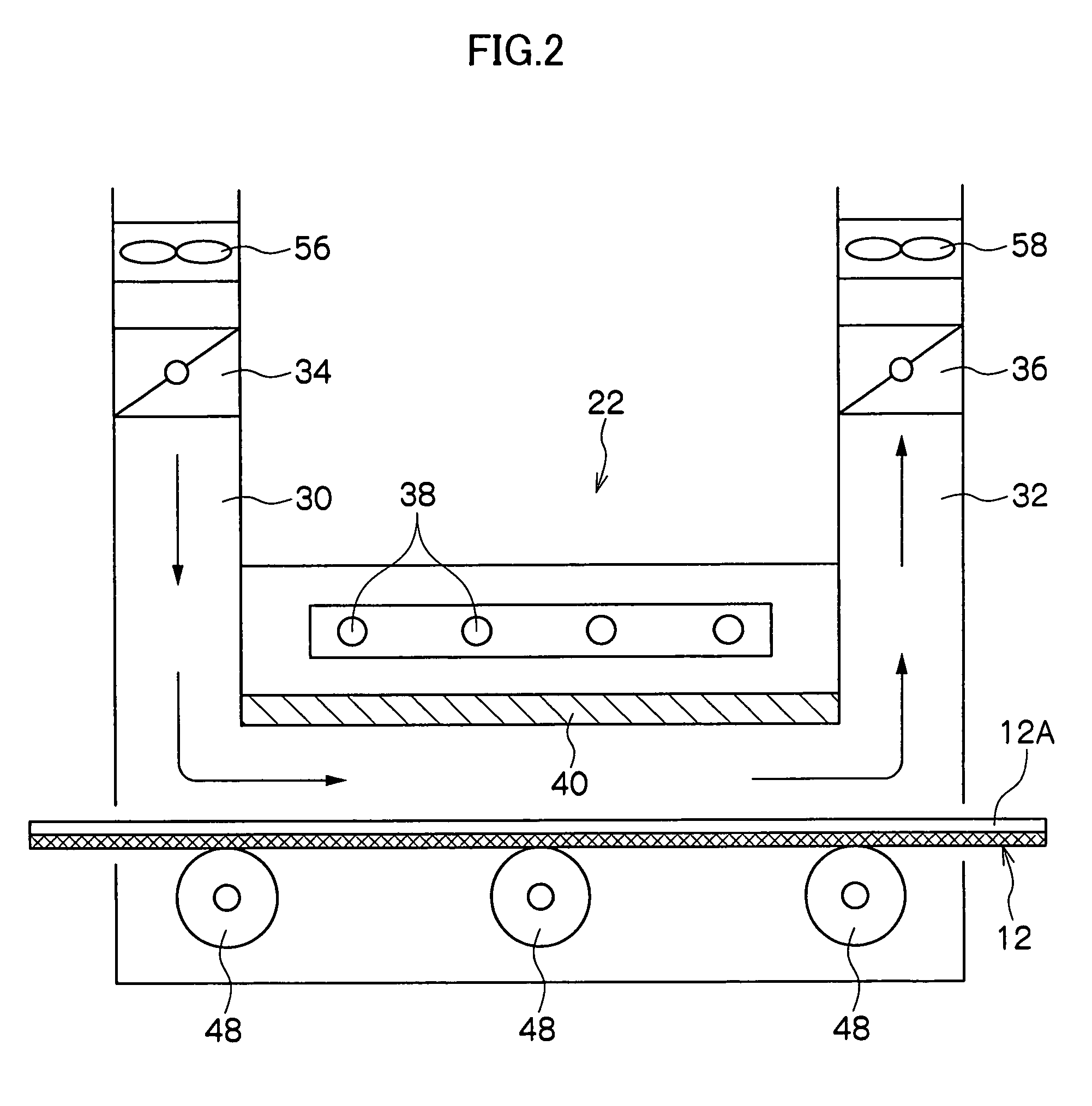
[0057]Table 1 shows the influence of the respective absence or presence of the filter 40 shown in FIGS. 2 and 3 upon the photosensitive coating layer 12A.

[0058]

TABLE 1Without filterWith filterBlocking rate of——Not lessnot lesswavelengths of notthan 25%than 30%more than 1 μmSeparation——10 mm10 mmdistance betweeninfrared radiatorsand filterSurface1000° C.200° C.1000° C.1000° C.temperature ofmid-far-mid-mid-infrared radiatorsinfraredinfraredinfraredinfraredraysraysraysraysOccurrence / non-Present onNonePresent onNoneoccurrence ofentirepart offoggingsurfacesurfaceDrying time8 seconds1810 seconds...


PUM

PropertyMeasurementUnit
wavelengthaaaaaaaaaa
energy wavelengthaaaaaaaaaa
separation distanceaaaaaaaaaa

Abstract

A drying device, which dries a photosensitive layer of a photosensitive planographic printing plate using infrared rays, includes an infrared emitting device and a filter that is arranged between the photosensitive planographic printing plate conveyed through the drying device and the infrared emitting device and that blocks a predetermined range of wavelength. More specifically, the filter is arranged between a web that is conveyed through the drying device and a mid-infrared radiator, so as to block 30% or more of wavelengths of 1 μm or less. As a result, fogging on a photosensitive coating layer can be prevented, and high heating efficiency can be achieved.

Description

CROSS-REFERENCE TO RELATED APPLICATION[0001]This application claims priority under 35 USC 119 from Japanese Patent Application No. 2004-018181, the disclosure of which is incorporated by reference herein.BACKGROUND OF THE INVENTION[0002]1. Field of the Invention[0003]The present invention relates to a drying device and a drying method for drying a photosensitive layer of a photosensitive planographic printing plate using infrared rays.[0004]2. Description of the Related Art[0005]Photosensitive planographic printing plates are produced in the following manner. At least one surface of an aluminum web, which is a belt-shaped aluminum thin plate, is grained, and a photosensitive coating liquid containing photosensitive resin or thermosensitive resin is applied to the surface and is dried to form a photosensitive layer.[0006]For example, in Japanese Patent Application Laid-Open (JP-A) No. 8-296962, as shown in FIG. 4, items to be heated are continuously transported on a conveyor 100 and ...

Claims


Application Information

Patent Timeline
Patent Type & Authority Patents(United States)
IPC IPC(8): G03D13/00F26B3/30F26B13/08G03F7/16G03D15/02G03F7/00G03F7/38
CPCG03D15/02
Inventor HAYASHI, KENJIHASHIGAYA, MANABU
Owner FUJIFILM HLDG CORP
Why Eureka
Try Eureka