High frequency edge mount connector

a high-frequency edge mount and connector technology, applied in the field of connectors, can solve the problems of reducing the size of the pin, affecting the quality of the connector, so as to improve the matching effect of impedance, reduce the loss of return, and tight seal

Active Publication Date: 2008-03-18
EMERSON NETWORK POWER CONNECTIVITY SOLUTIONS
View PDF9 Cites 19 Cited by
  • Summary
  • Abstract
  • Description
  • Claims
  • Application Information

AI Technical Summary

Benefits of technology

[0007]The present invention is defined by the following claims, and nothing in this section should be taken as a limitation on those claims. By way of introduction, the preferred embodiments described below relate to a high frequency edge mount connector. The edge mount connector includes a housing forming an opening. The present invention is capable of achieving both a low return loss and insertion loss. The connector includes a housing that forms an opening and a signal carrier in the housing. The signal carrier has a pin which extends through the opening. The connector also includes an insulator in the housing and surrounding the signal carrier, wherein the insulator has a outer portion surrounding the pin and extending through the opening. By extending the insulator through the opening, a tight seal can be created when the connector is pressed against a circuit board. The seal allows for improved impedance matching for a signal traveling between the connector and the circuit board.

Problems solved by technology

Reducing the size of the pin, however, complicates the attachments of the pin to the signal trace of the circuit board.
Since the pin is smaller, damage to the pin may occur if the pin is not handled properly when placed in contact with the signal trace.
Additionally, aligning the pin on the signal trace is made more difficult when the pin is made smaller.
In addition to complicating the attachment of the pin to the circuit board, as the wavelength of the high frequency signals decreases, it becomes more difficult to achieve both low return loss and insertion loss when transitioning the high frequency signal from the signal line to the circuit board.

Method used


Image

  • High frequency edge mount connector
  • High frequency edge mount connector
  • High frequency edge mount connector

Examples


Embodiment Construction

[0028]While the present invention may be embodied in many different forms, there is shown in the drawings and discussed herein a few specific embodiments with the understanding that the present disclosure is to be considered only as an exemplification of the principles of the invention and is not intended to limit the invention to the embodiments illustrated.

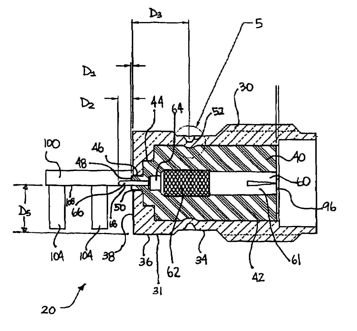
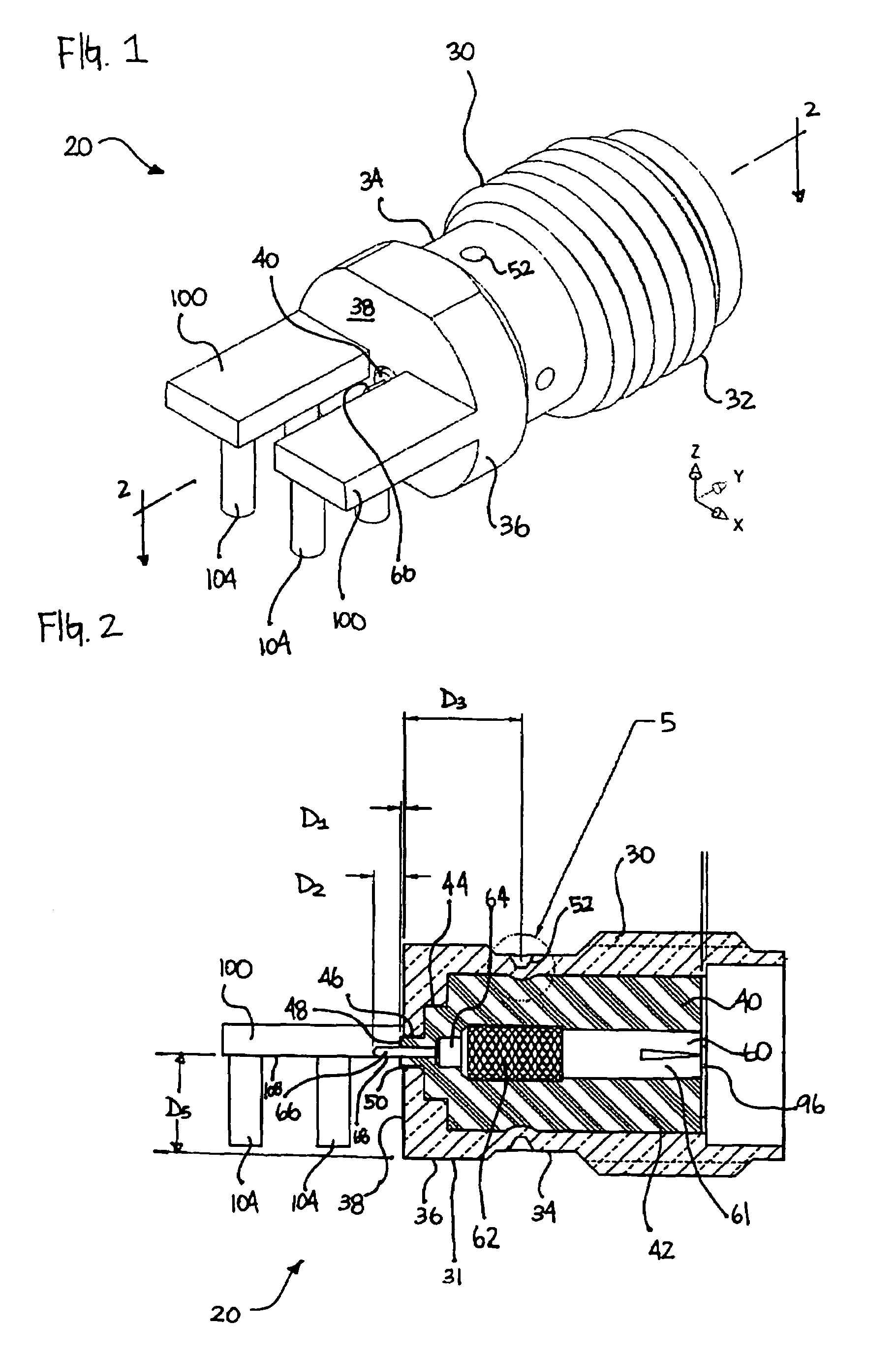
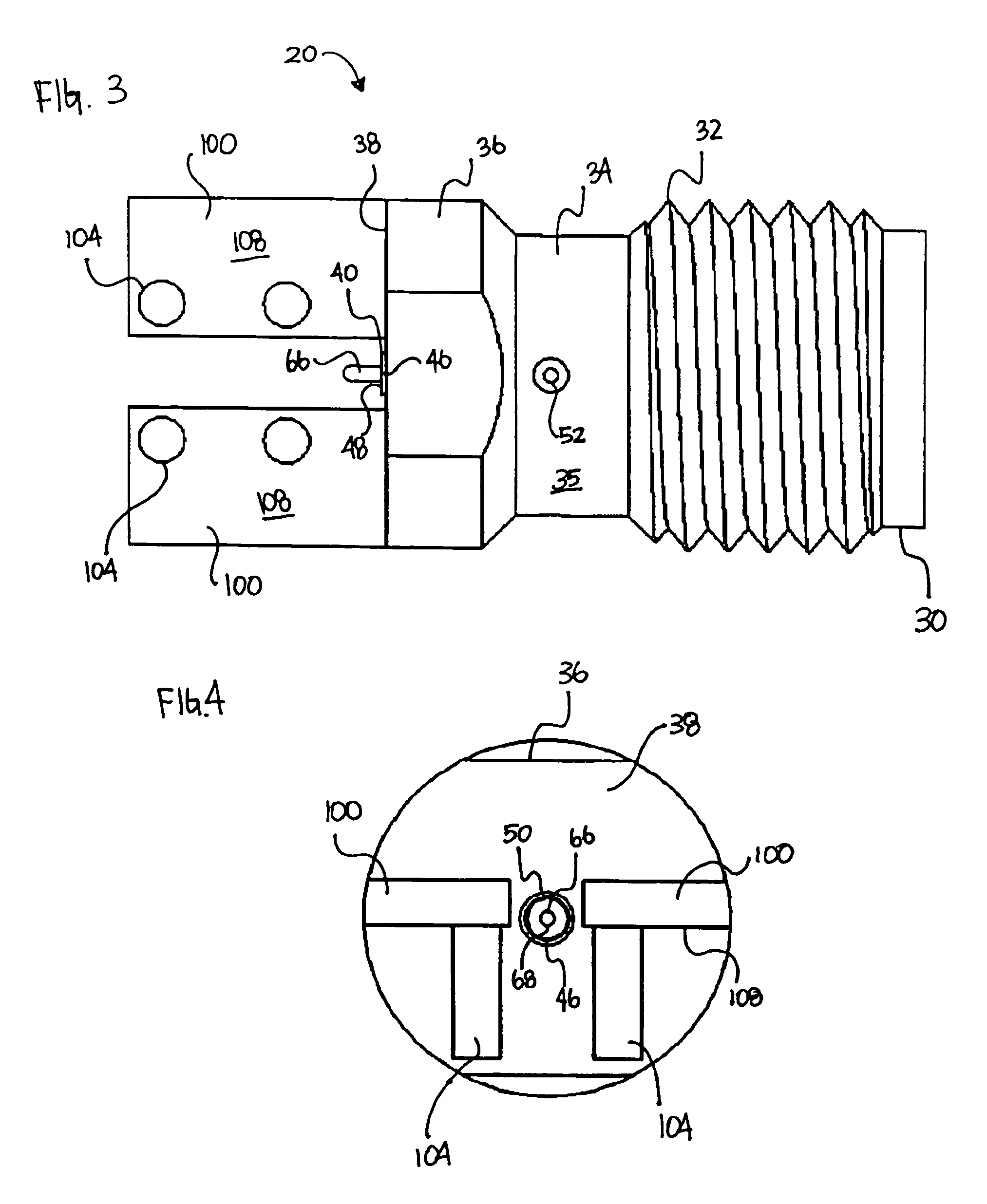
[0029]The present invention describes an edge mount connector for high frequency signals that is capable of achieving both low a return loss and insertion loss. The connector includes a housing that forms an opening and a signal carrier in the housing. The signal carrier has a pin which extends through the opening. The connector also includes an insulator in the housing and surrounding the signal carrier, wherein the insulator has a outer portion surrounding the pin and extending through the opening. By extending the insulator through the opening, a tight seal can be created when the connector is pressed against a circuit board....


PUM


Abstract

High frequency edge mount connector apparatus comprises a connector including a housing that forms an opening and a signal carrier in the housing allowing for low return loss and low insertion loss. The signal carrier has a pin which extends through the opening. The connector also includes an insulator in the housing and surrounding the signal carrier, wherein the insulator has a outer portion surrounding the pin and extending through the opening. By extending the insulator through the opening, a tight seal can be created when the connector is pressed against a circuit board. The seal allows for improved impedance matching for a signal traveling between the connector and the circuit board.

Description

BACKGROUND OF THE INVENTION[0001]This invention relates generally to connectors, and in particular, to a high frequency edge mount launch connector for transitioning coaxial to planar microwave signals.[0002]High frequency edge mount launch connectors may be used to transition high frequency signals from coaxial to planar transmission line structures. High frequency signals include signals which are greater than 500 megahertz and extend up through the K-band, such as microwave signals. Applications which require the use of high frequency signals require unique connectors and circuit boards. Examples of some of these applications include cellular and pager linear power amplifiers, cellular handset filters, and DBS low-noise block down converters. High frequency signals typically consist of time varying electromagnetic fields which may be able to induce currents on metal surfaces.[0003]In order to transition or “launch” high frequency signals from a cylindrically shaped coaxial cable ...

Claims


Application Information

Patent Timeline
Patent Type & Authority Patents(United States)
IPC IPC(8): H01R12/00H01R12/16H01R13/52H01R13/646H01R13/648
CPCH01R13/521H01R23/6873H01R24/50H01R12/721H05K2203/1189H01R13/658
Inventor KEREKES, JIM
Owner EMERSON NETWORK POWER CONNECTIVITY SOLUTIONS
Why Eureka
Try Eureka