Projector and liquid crystal panel unit for use in projector with optical sheet edge-tilting mechanism

a technology of liquid crystal panel and projector, which is applied in the field of projectors, can solve the problems of unnecessary stock, partial light leakage in a portion, etc., and achieve the effects of avoiding optical axis shift, high contrast, and simplifying configuration

Active Publication Date: 2008-03-18
SANYO ELECTRIC CO LTD
View PDF10 Cites 6 Cited by
  • Summary
  • Abstract
  • Description
  • Claims
  • Application Information

AI Technical Summary

Benefits of technology

[0022]In the configuration according to the first aspect of the present invention, the slow axis of the liquid crystal molecules in the optical compensation sheet seen from the optical axis direction can be set almost parallel with the alignment direction of the liquid crystal molecules of the liquid crystal panel. In addition, the apparent slow axis of the optical compensation sheet can be made coincide with the slow axis in the optical axis direction of the liquid crystal molecules in the liquid crystal panel. Consequently, a uniform image having high contrast between black and white can be projected.
[0023]With the configuration of the present invention, by disposing the optical compensation sheet which can be adjusted by being tilted from the optical axis and can be adjusted by being swung in a plane orthogonal to the optical axis on the light incidence side of the liquid crystal panel, a shift of the optical axis can be prevented.
[0023]With the configuration of the present invention, by disposing the optical compensation sheet which can be adjusted by being tilted from the optical axis and can be adjusted by being swung in a plane orthogonal to the optical axis on the light incidence side of the liquid crystal panel, a shift of the optical axis can be prevented.
[0025]With the configuration of the present invention, the configuration can be simplified by integrating the polarizing plate and the optical compensation sheet, so that miniaturization can be achieved.
[0023]With the configuration of the present invention, by disposing the optical compensation sheet which can be adjusted by being tilted from the optical axis and can be adjusted by being swung in a plane orthogonal to the optical axis on the light incidence side of the liquid crystal panel, a shift of the optical axis can be prevented.

Problems solved by technology

As a result, a problem occurs that partial light leak occurs in a portion to be inherently displayed in black.
Therefore, it is necessary to prepare optical compensation sheets having various optical axis, and it causes a problem such as occurrence of unnecessary stocks.

Method used


Image

  • Projector and liquid crystal panel unit for use in projector with optical sheet edge-tilting mechanism
  • Projector and liquid crystal panel unit for use in projector with optical sheet edge-tilting mechanism
  • Projector and liquid crystal panel unit for use in projector with optical sheet edge-tilting mechanism

Examples


first embodiment

[0040]An embodiment of the present invention will be described in detail hereinbelow with reference to FIGS. 1 to 7.

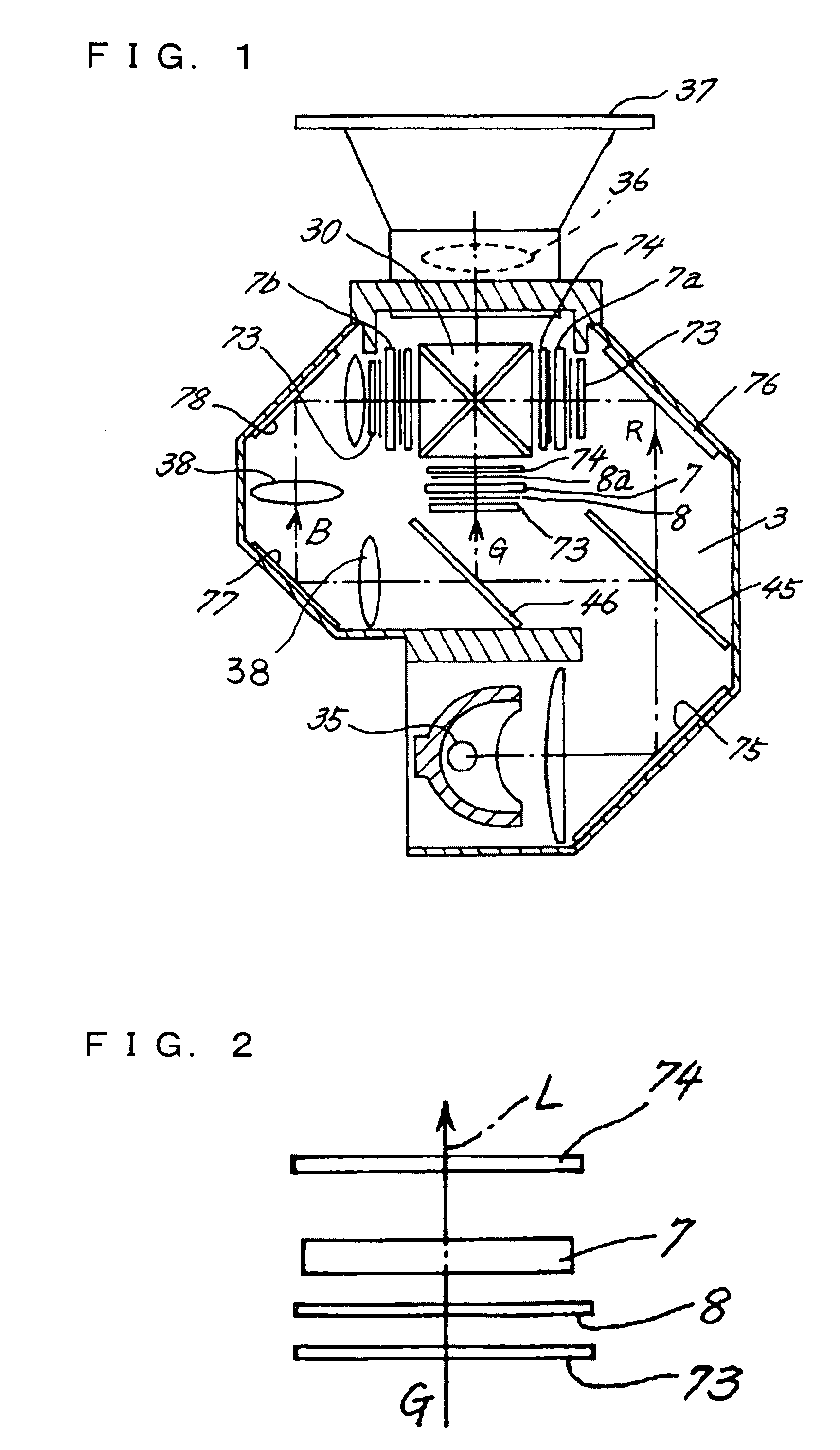
[0041]FIG. 1 is a plan view showing a projector according to the present invention. The projector has three liquid crystal panels 7, 7a, and 7b corresponding to green (G) light, red (R) light, and blue (B) light as the three primary colors of light on a chassis 3. The liquid crystal panels are irradiated with strong light from a light source 35, light fluxes passed through the liquid crystal panels are combined, and an image is formed via a projection lens 36.

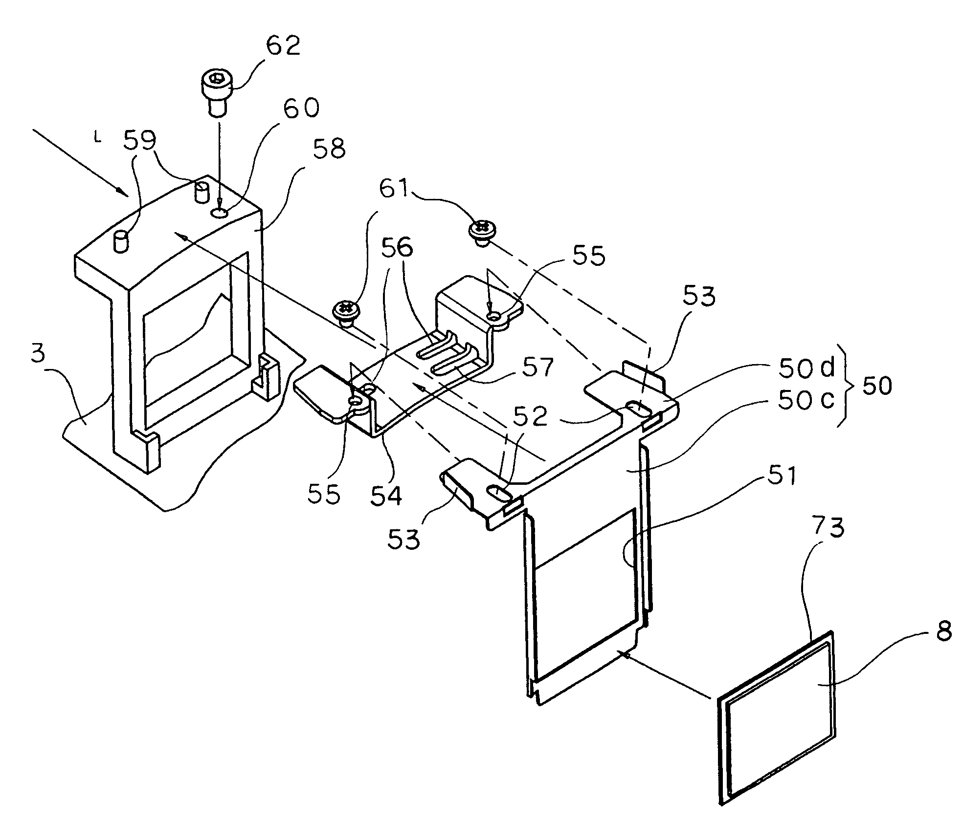
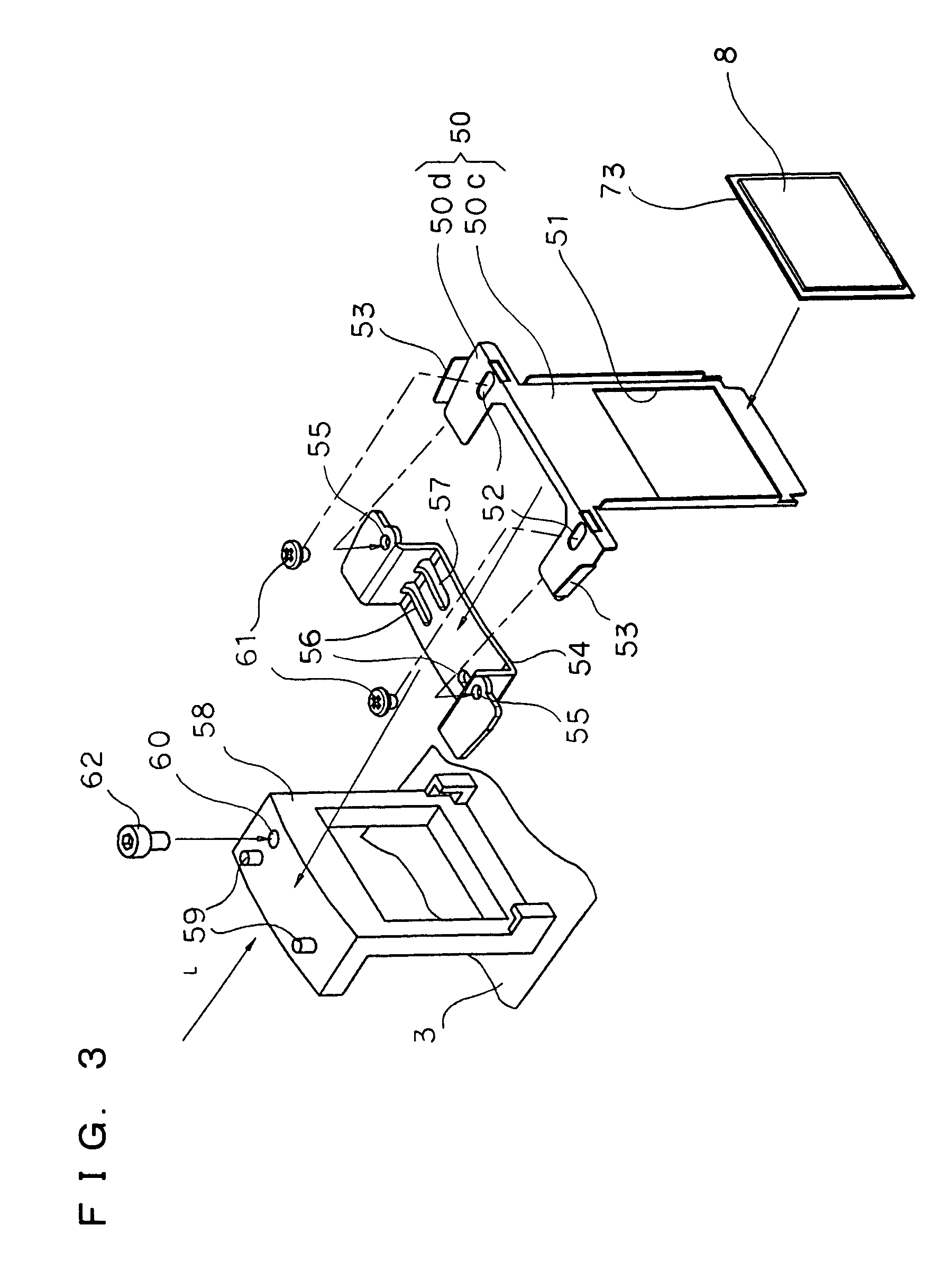
[0042]In the chassis 3, the liquid crystal panels 7a and 7b corresponding to the red (R) light and the blue (B) light are disposed while sandwiching the optical axis of the projection lens 36, and a prism body 30 is disposed between the liquid crystal panels 7a and 7b. On the side opposite to the projection lens 36 over the prism body 30, the liquid crystal pane 17 corresponding to the green (G) light is disposed....

second embodiment

[0067]FIGS. 8 to 10 show a second embodiment of the present invention. The same reference numerals are designated to the same parts as those of the first embodiment and their description will not be repeated. The assisting member 54 is attached to a swing member 50a. The assisting member 54 is the same as that in the first embodiment.

[0068]The optical compensation sheet 8 of the second embodiment is disposed on the light incidence side of the liquid crystal panel 7 in a manner similar to the first embodiment. The polarizing plate 73 is attached to a moving member 65, and the moving member 65 is constructed swingable in a plane orthogonal to the optical axis L. The swing member 50a to which the optical compensation sheet 8 is attached is constructed swingable in the plane orthogonal to the optical axis L with respect to the moving member 65, and the normal H of the swing member 50a is adjustable so as to be tilted from the optical axis L.

[0069]The optical compensation sheet 8 is atta...


PUM

PropertyMeasurementUnit
birefringenceaaaaaaaaaa
electric fieldaaaaaaaaaa
transparentaaaaaaaaaa

Abstract

A projector includes: a liquid crystal panel in which liquid crystal molecules to be irradiated with light from a light source are sealed; a polarizing plate disposed in a position to face the liquid crystal panel; and an optical compensation sheet disposed between the polarizing plate and the liquid crystal panel and compensating birefringence of the liquid crystal molecules. The optical compensation sheet can be adjusted by being swung in a plane orthogonal to the optical axis, and its normal can be adjusted so as to be tilted from the optical axis.

Description

BACKGROUND OF THE INVENTION[0001]1. Field of the Invention[0002]The present invention relates to a projector in which an optical compensation sheet is disposed between a liquid crystal panel and a polarizing plate.[0003]2. Description of the Related Art[0004]FIGS. 11A and 11B are exploded perspective views of a conventional liquid crystal panel 7 and polarizing plates 73 and 74 sandwiching the liquid crystal panel 7. FIG. 11A shows a state where no electric field is applied to the liquid crystal panel 7, and FIG. 11B shows a state where an electric field is applied to the liquid crystal panel 7. As it is known, the polarizing plates 73 and 74 permit passage of one of two pieces of polarized light orthogonal to each other, and have vibration planes of polarized light which is permitted to pass. The vibration planes are deviated from each other by 90 degrees.[0005]The liquid crystal panel 7 is constructed by sealing liquid crystal molecules 90 in transparent display substrates 70 and ...

Claims


Application Information

Patent Timeline
Patent Type & Authority Patents(United States)
IPC IPC(8): G02F1/1335
CPCG02F1/133308G02F1/13363H04N9/3105H04N9/317G02F2413/01G02B5/30
Inventor YOSHIMURA, TAICHIFURUTA, YOSHIHIRO
Owner SANYO ELECTRIC CO LTD
Why Eureka
Try Eureka