Fiber optic drop cable slack storage receptacle

a drop cable and storage receptacle technology, applied in the field of fiber optic drop cable storage receptacles, can solve the problems of high installation cost, high customer number, and discourage service providers from deploying continuous fiber optic networks extending from their central office facilities, so as to facilitate the deployment and installation of optical fiber, facilitate long-term trouble-free service, and facilitate the effect of optical fiber deploymen

Active Publication Date: 2008-03-18
CORNING OPTICAL COMM LLC
View PDF26 Cites 160 Cited by
  • Summary
  • Abstract
  • Description
  • Claims
  • Application Information

AI Technical Summary

Benefits of technology

[0008]To achieve the foregoing and other objects, and in accordance with the purposes of the invention as embodied and broadly described herein, the present invention provides various embodiments of a fiber optic drop cable slack storage receptacle for storing and protecting an excess length of a fiber optic drop cable deployed in an optical communications network. In particular, the present invention provides various embodiments of a fiber optic drop cable storage receptacle for storing and protecting the excess length of a pre-connectorized fiber optic drop cable deployed between a connection terminal and a subscriber network interface device (NID) in an optical communications network. The slack storage receptacle described herein substantially reduces the additional cost of manufacturing, shipping and deploying custom lengths of pre-connectorized fiber optic drop cables to a subscriber premises. Further, the slack storage receptacle described herein allows a field technician to install a pre-connectorized fiber optic drop cable at a subscriber premises and to store the drop cable slack, while providing protection to the drop cable from adverse environmental conditions.
[0009]To facilitate the deployment of optical fiber to the subscriber premises, the slack storage receptacle of the present invention is operable for storing the excess length of fiber optic drop cable that extends between a network connection terminal and the subscriber premises. In one exemplary embodiment, the present invention is a slack storage receptacle that facilitates the deployment and installation of optical fiber to a NID mounted on the exterior wall of the subscriber premises. The slack storage receptacle includes a housing and a drawer that is adapted to cooperate in sliding engagement with the housing. To facilitate long-term, trouble free service, the slack storage receptacle is configured so as to not interfere with the operational functions of the NID, and is further configured to store fiber optic drop cable slack while maintaining the minimum bend radius of the drop cable. The housing includes a substantially planar rear panel having at least one recessed mounting port for receiving a fastener to secure the housing to the exterior wall of the subscriber premises, a top wall and a bottom wall. The top and bottom walls each have a lip extending therefrom and projecting inwardly towards the opposite wall. Further, at least one of the top and bottom walls of the housing has a plurality of biased locking pins for securing the drawer in an opened configuration and a closed configuration relative to the housing. Preferably, the pins are laterally offset and located at opposing ends of the wall to which they are affixed. Extending from the top and bottom walls of the first housing are mounting brackets for mounting the NID or a cover plate onto the housing.
[0010]The drawer includes a substantially planar rear wall, a top wall, a bottom wall and opposed side walls, which together define an interior cavity for retaining the drop cable slack. Extending from each wall is a lip that projects inwardly towards the interior cavity of the drawer. The rear wall of the drawer has at least one aperture disposed therein that is coincident with the at least one mounting port with the drawer in the closed configuration to permit a field technician to access the fastener within the mounting port. A respective one of the top wall and the bottom wall of the drawer has a corresponding plurality of openings therethrough, one of which is coincident with a corresponding pin of the housing in the opened configuration and the closed configuration. The respective top or bottom wall is further provided with guiding tabs at the opposed ends thereof for permitting the drawer to travel past the corresponding pin while being moved from the opened configuration to the closed configuration. When the drawer is slidably engaged with the housing, at least one, and preferably only one, of the pins of the housing engages the corresponding opening in the drawer to secure the receptacle in the closed configuration. When the drawer is in the opened configuration, a field technician can easily arrange one or more coils of the drop cable slack therein so that the outward bias of the drop cable coils presses the drop cable slack against the top wall, the bottom wall and the side walls of the drawer, thereby retaining the drop cable slack within the drawer of the slack storage receptacle, while maintaining a minimum bend radius of the fiber optic drop cable.

Problems solved by technology

Despite the many advantages, extremely high installation costs have discouraged service providers from deploying continuous fiber optic networks extending from their central office facilities all the way to subscriber premises.
Along the primary distribution lines of a communications network, the volume of traffic and the number of customers often justify the high installation cost of optical fiber.
However, thus far, the additional cost of deploying optical fiber to remote, individual subscriber premises has far outweighed the potential benefits to service providers.
However, the pre-connectorized drop cable must be manufactured in either custom or preselected standard lengths, the former being impractical due to the higher manufacturing costs so that the latter is a preferred solution in most instances.
A problem which then exists is where and how to store the excess length of drop cable that results when deploying, for example, a standard 108-foot drop cable when the length of the drop cable actually needed is only 175 feet.
Service providers have long desired to deploy pre-connectorized drop cables in order to reduce field labor and installation costs, but thus far have not been presented with an effective manner in which to store the excess length of the drop cable (also referred to herein as drop cable slack).

Method used


Image

  • Fiber optic drop cable slack storage receptacle
  • Fiber optic drop cable slack storage receptacle
  • Fiber optic drop cable slack storage receptacle

Examples


Embodiment Construction

[0024]The present invention will now be described more fully hereinafter with reference to the accompanying drawings in which exemplary embodiments of the invention are shown. However, this invention may be embodied in many different forms and should not be construed as limited to the embodiments set forth herein. These exemplary embodiments are provided so that this disclosure will be both thorough and complete, and will fully convey the scope of the invention to those skilled in the art. Like reference numbers refer to like elements throughout the various drawings.

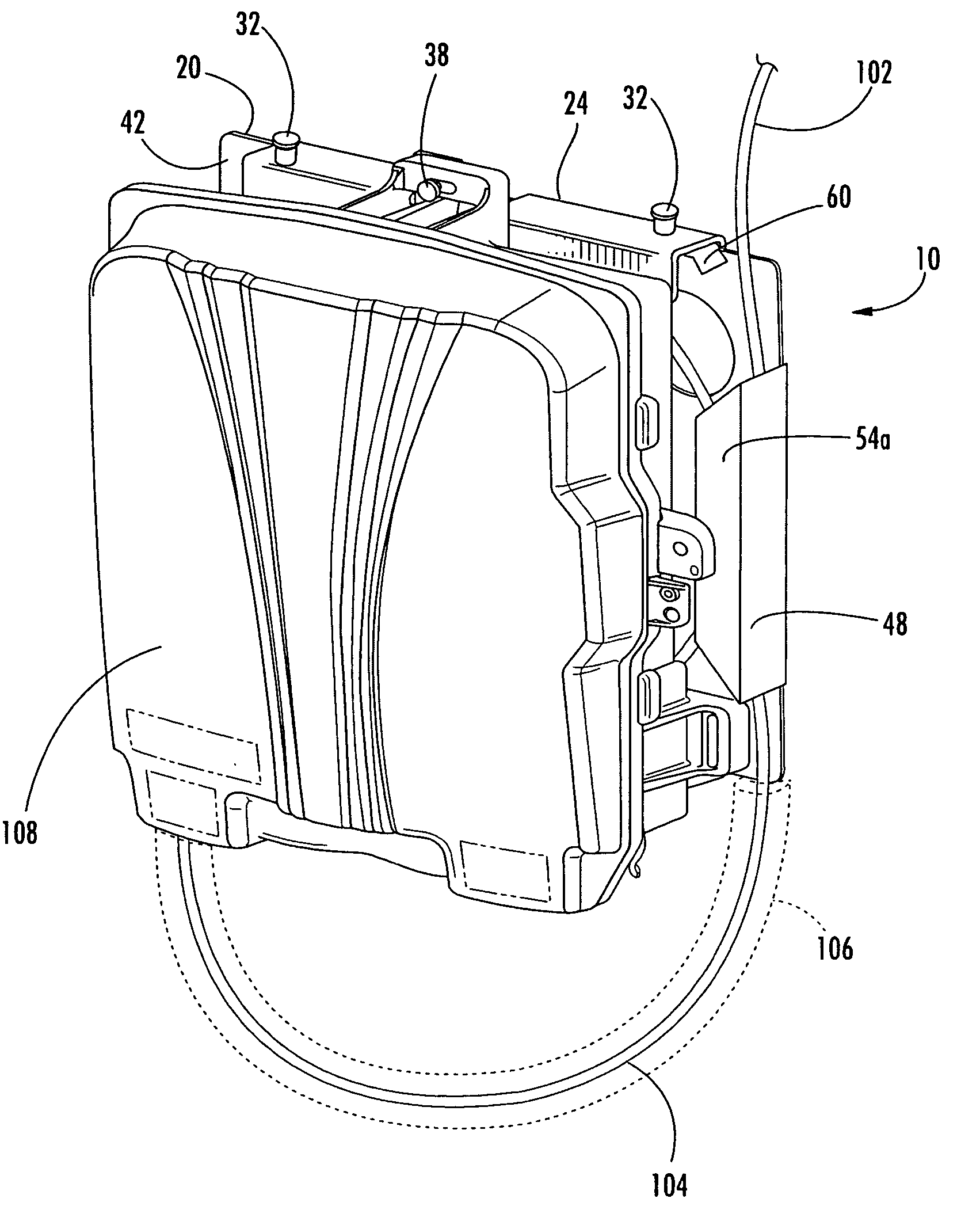
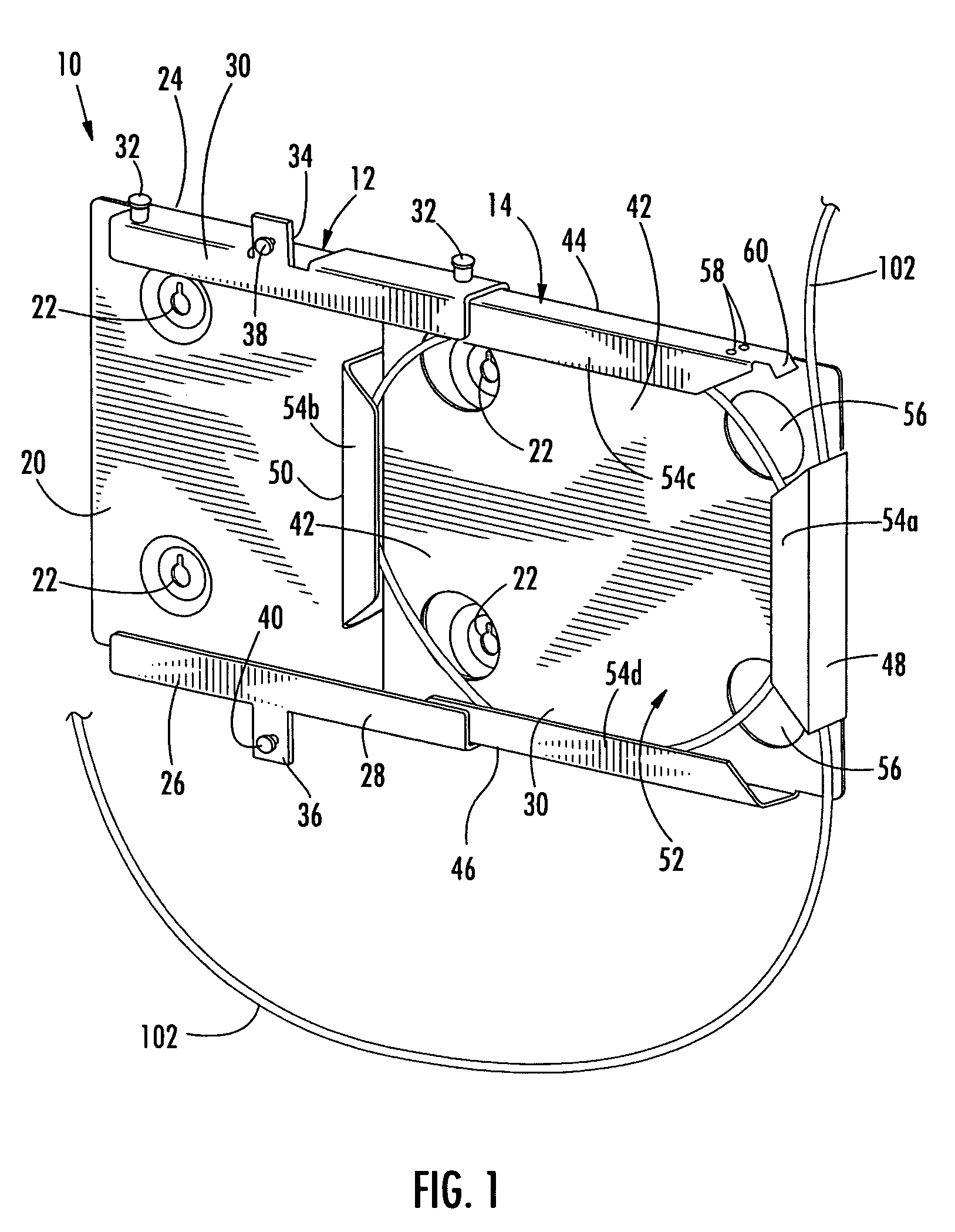
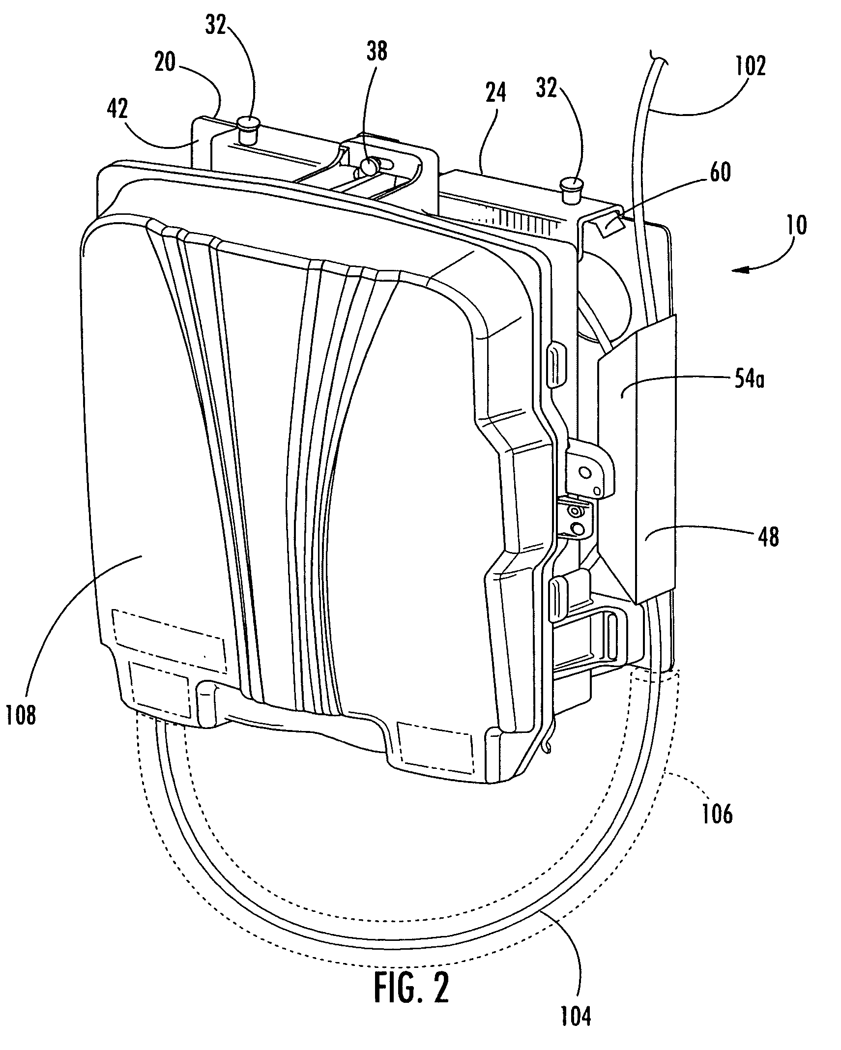
[0025]The present invention provides a fiber optic drop cable slack storage receptacle for storing and protecting an excess length of a pre-connectorized fiber optic drop cable in an optical communications network. As is well known and understood in the art, a connectorized fiber optic drop cable comprises a hollow cable sheath or jacket housing at least one flexible transport tube containing one or more optical fibers. ...


PUM


Abstract

A slack storage receptacle for storing an excess length of a pre-connectorized fiber optic drop cable extending between an optical connection terminal and a network interface device (NID) includes a housing and a storage means disposed within the housing for receiving the drop cable such that the drop cable slack is stored external to the NID. The slack storage receptacle may be secured to an exterior wall of a subscriber premises and the NID mounted thereon. Alternatively, the slack storage receptacle may be positioned around and formed to the NID. Alternatively, the slack storage receptacle may be buried in the ground adjacent the NID. The drop cable slack may be wound onto the storage means after deployment. Alternatively, the slack storage receptacle may be pre-assembled, shipped to the subscriber premises, and the drop cable unwound from the storage means with the drop cable slack remaining wound on the storage means.

Description

BACKGROUND OF THE INVENTION[0001]1. Field of the Invention[0002]The present invention relates generally to a storage receptacle for a fiber optic drop cable, and more particularly, to a fiber optic drop cable slack storage receptacle for storing and protecting an excess length of a pre-connectorized fiber optic drop cable in an optical communications network.[0003]2. Description of the Related Art[0004]The telecommunications industry has recognized the many advantages of fiber optic cable, including a significantly higher bandwidth and greater performance and reliability than conventional copper wire systems. Despite the many advantages, extremely high installation costs have discouraged service providers from deploying continuous fiber optic networks extending from their central office facilities all the way to subscriber premises. As used herein, “fiber-to-the-premises” (FTTP) refers to the deployment of an optical fiber network that extends continuously to the subscriber premises...

Claims


Application Information

Patent Timeline
Patent Type & Authority Patents(United States)
IPC IPC(8): G02B6/00B65D85/00
CPCG02B6/4453G02B6/4457G02B6/4466G02B6/475
Inventor BLOODWORTH, STEPHEN G.GRUNWALD, BRAD N.KEENUM, JOHN A.NAPIORKOWSKI, JOHN J.REAGAN, JASON B.STABER, HARLEY J.TENHOLDER, RODGER A.VO, CHANH C.COOKE, TERRY L.KLAVUHN, TORY A.LUTHER, JAMES P.
Owner CORNING OPTICAL COMM LLC
Why Eureka
Try Eureka