Eureka AIR delivers breakthrough ideas for toughest innovation challenges, trusted by R&D personnel around the world.

Latch device for a door of an electric household appliance in particular a dishwashing machine

a technology for electric household appliances and latch devices, which is applied in the direction of carpet fasteners, wing knobs, dwelling equipment, etc., can solve the problems of not always reliable, complex, expensive, and unusable latch devices, and achieves low manufacturing and assembly costs and high reliability.

Active Publication Date: 2008-03-25
ITW IND COMPONENTS SRL
View PDF7 Cites 42 Cited by
  • Summary
  • Abstract
  • Description
  • Claims
  • Application Information

AI Technical Summary

Benefits of technology

[0008]It is an object of the present invention to eliminate the drawbacks of the aforementioned known devices by providing a latch device enabling the user to open the door of the appliance without a handle, by simply pressing a control button, and which at the same time permits low-cost manufacture and assembly, compactness, and a high degree of reliability of both the device itself and the appliance as a whole.
[0017]At this point, the door can be fully opened by gripping the half-open edge, whereas, even with the control button released and restored to the rest position, the contact member is prevented from returning to the start position.

Problems solved by technology

Since a certain amount of force must therefore be applied by the user on the door to open it, the door must normally be equipped with a handle or other gripping devices, which are unsightly and bulky.
The latch devices required in this case, however, are complex, expensive, and not always reliable (on account of the necessity to ensure fast stoppage of the wash cycle).
Such a solution is obviously unsatisfactory, both in terms of the high cost involved and the impossibility of opening the door in the event of power failure.

Method used


Image

  • Latch device for a door of an electric household appliance in particular a dishwashing machine
  • Latch device for a door of an electric household appliance in particular a dishwashing machine
  • Latch device for a door of an electric household appliance in particular a dishwashing machine

Examples


Embodiment Construction

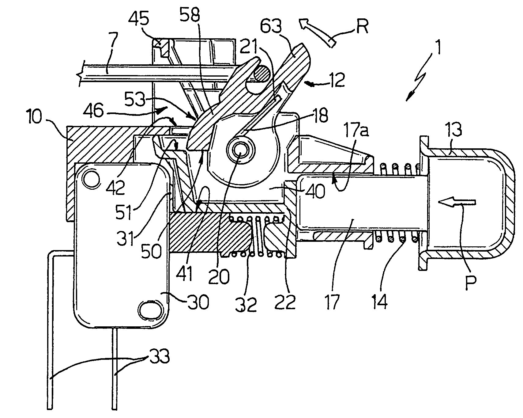
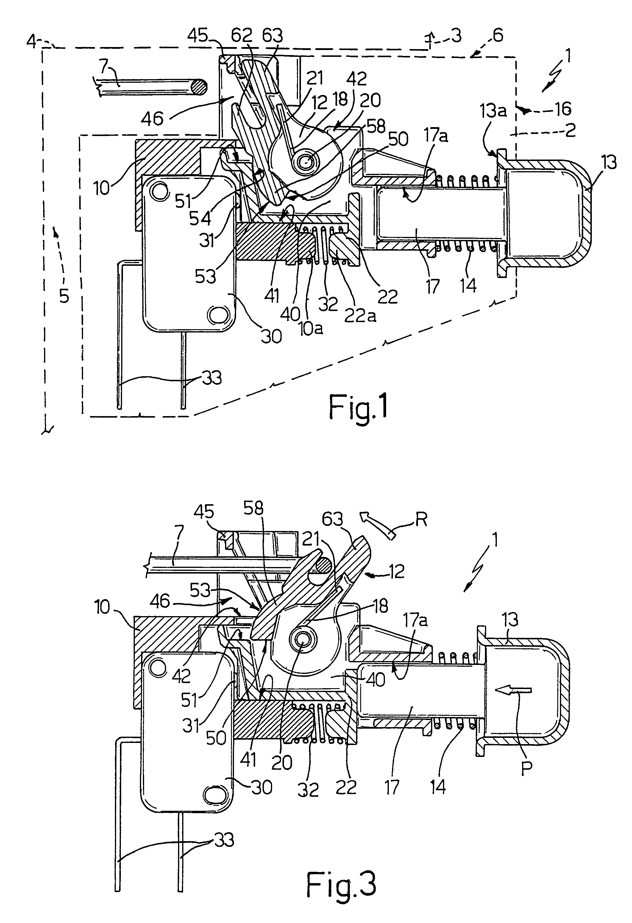
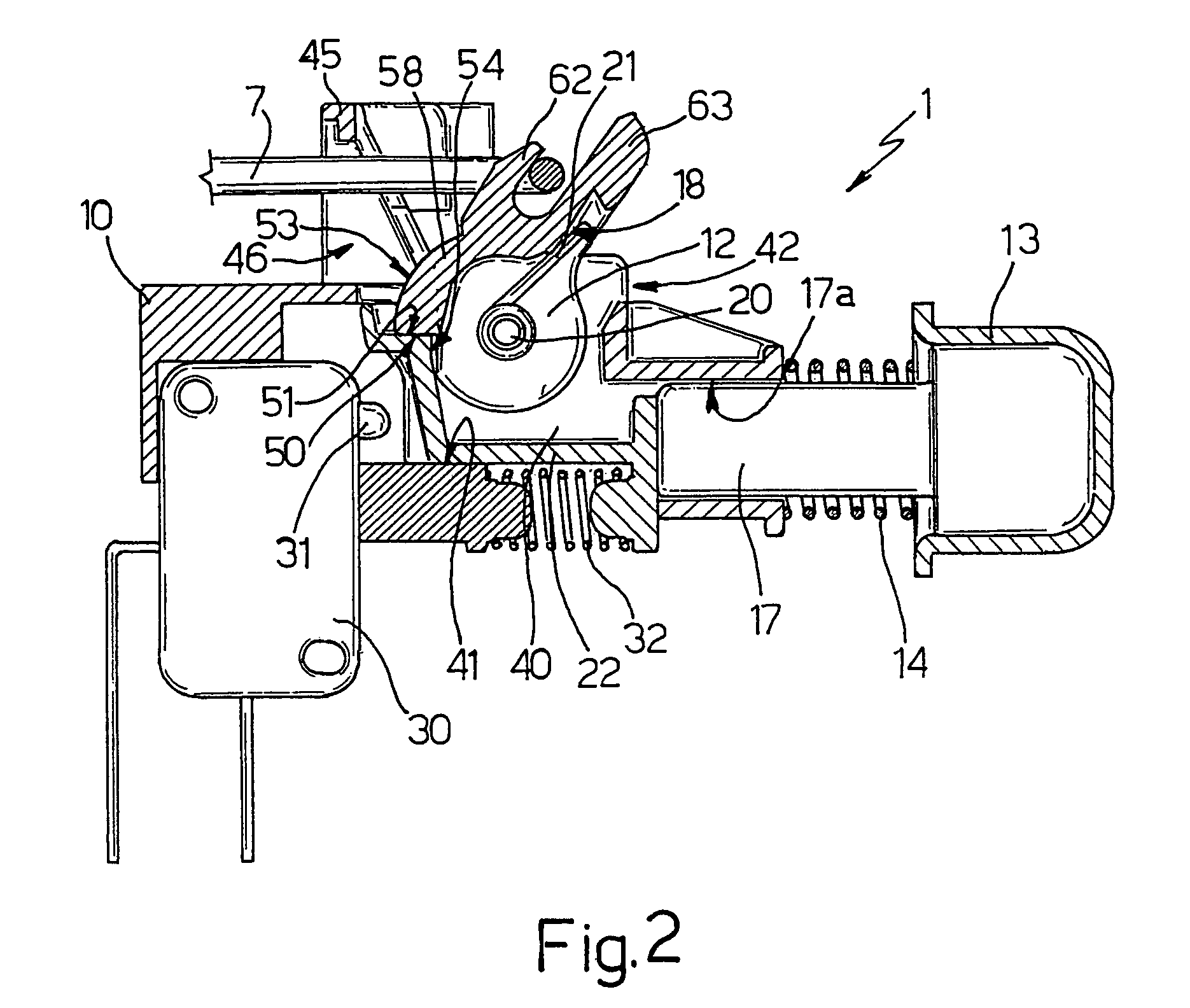
[0023]Number 1 in FIGS. 1 to 3 indicates as a whole a latch device for a door 2 of an electric household appliance 3, in particular a swing door 2 of a dishwashing machine 3, of which the top portion of a casing 4 defining a door opening 5 is shown by a dash line.

[0024]In the non-limiting embodiment shown, device 1 is fitted, in use, to a top edge 6 of door 2, facing a fixed known striker 7 fixed integrally to casing 4 at the top of door opening 5.

[0025]Device 1 comprises a support 10 fixable to door 2; a substantially known fork-shaped latch member 12 fitted in rotary manner to support 10 in such a position as to cooperate, in use, with striker 7; and a control button 13 fitted to support 10 to slide in opposition to first elastic means 14, so as to be positioned, in use, at a front outer surface 16 of door 2. In the example shown, a rear end 17 of button 13 is guided and slides inside a through seat 17a of support 10 facing surface 16 in use, and elastic means 14 comprise a helica...


PUM


Abstract

A latch device for a swing door of an electric household appliance, includes a support fixable to the door; a fork-shaped latch member fitted in rotary manner to the support to cooperate, in use, with a fixed striker of the appliance; and a control button fitted to the support to slide in opposition to a first elastic element. The latch member is movable, in opposition to a second elastic element on the support, between a first operating position, in which it does not engage the striker, and a second operating position, in which it does engage the striker. A contact member is fitted to the support to slide parallel to the control button in opposition to a third elastic element, and operatively interposed between the control button and the latch member to selectively lock the latch member in the second operating position, and to be selectively locked by the latch member when the latch member is in the first operating position.

Description

RELATED APPLICATIONS[0001]The present application is based on, and claims priority from, Italian Application Number TO2004A 000534, filed Jul. 30, 2004, the disclosure of which is hereby incorporated by reference herein in its entirety.[0002]The present invention relates to a latch device for a door of an electric household appliance, and in particular to a latch device for a swing door of a dishwashing machine, by which the door can be opened by simply pressing a control button.BACKGROUND OF THE INVENTION[0003]As is known, a work compartment of an electric household appliance, such as a dishwashing compartment, is closed, when the appliance is running, by a normally hinged door. The door of a dishwashing machine is normally mounted to swing vertically, and the user must be able to open the door during the wash cycle to load more dishes (even only for rinsing) or detergent additives, or even simply to check on progress of the washing cycle. In which case, the wash cycle must be stop...

Claims


Application Information

Patent Timeline
Patent Type & Authority Patents(United States)
IPC IPC(8): E05C3/06
CPCA47L15/4259E05B1/0038E05C3/24Y10S292/37Y10T292/1047
Inventor ALA, GIAN BATTISTA
Owner ITW IND COMPONENTS SRL
Why Eureka
Eureka Blog
Learn More