
Radiation isocenter measurement devices and methods and 3-D radiation isocenter visualization systems and related methods

a technology of measurement device and visualization system, which is applied in the field of radiation isocenter measurement device and method and 3d radiation isocenter visualization system, can solve problems such as harm to the healthy tissue surrounding the diseased tissu

Inactive Publication Date: 2008-03-25
EAST CAROLINA UNIVERISTY
View PDF12 Cites 26 Cited by
  • Summary
  • Abstract
  • Description
  • Claims
  • Application Information

AI Technical Summary

Benefits of technology

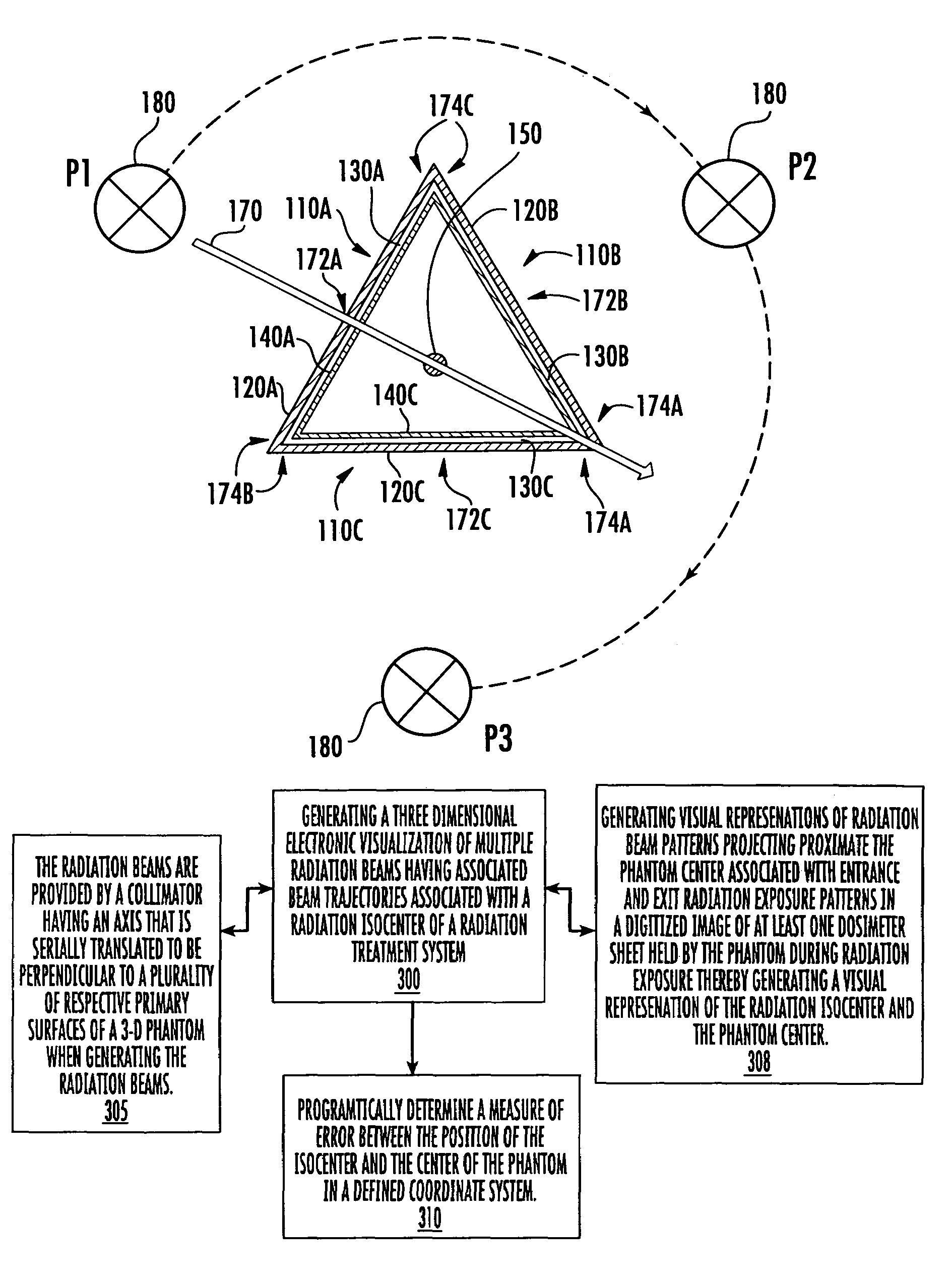
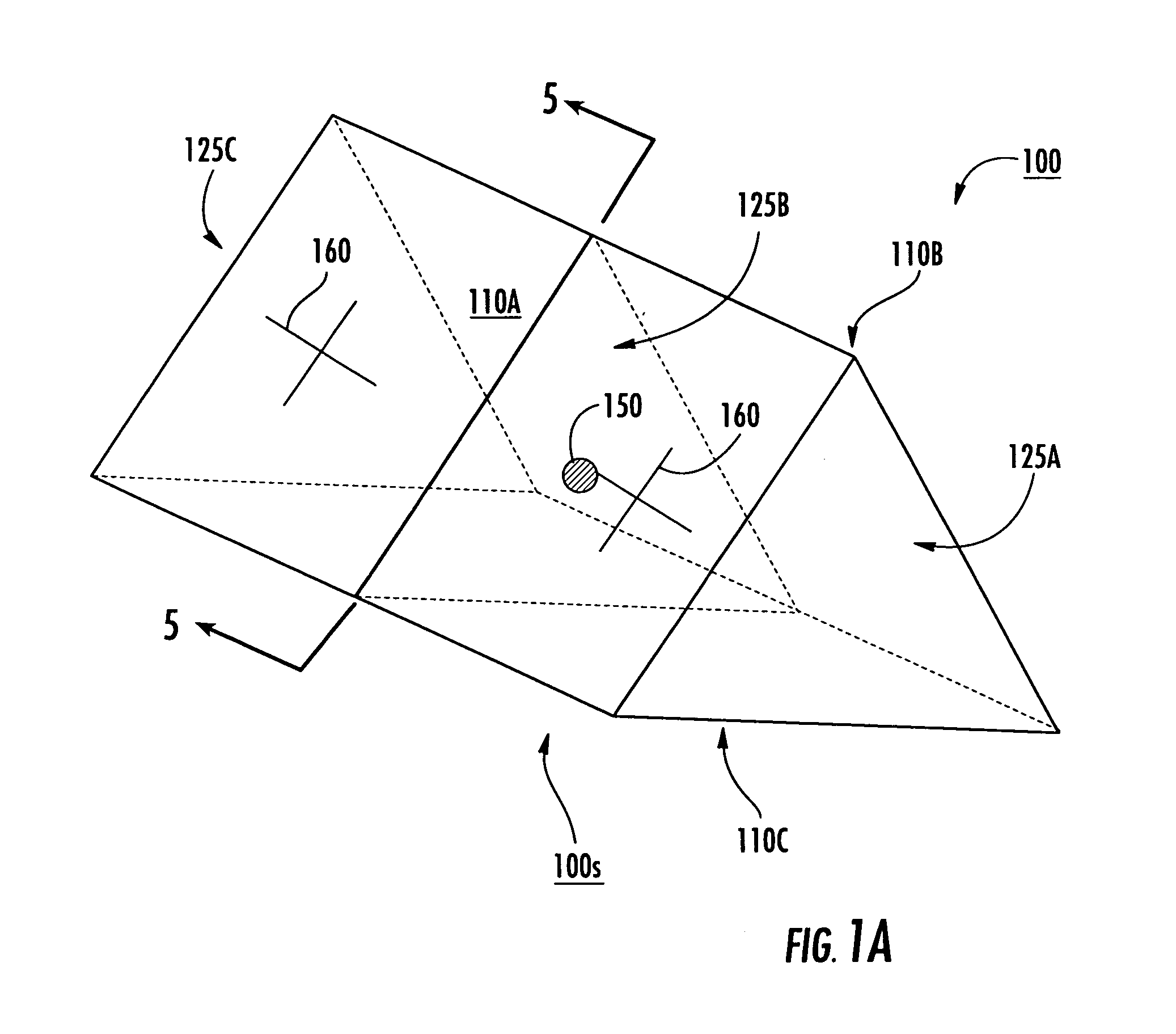
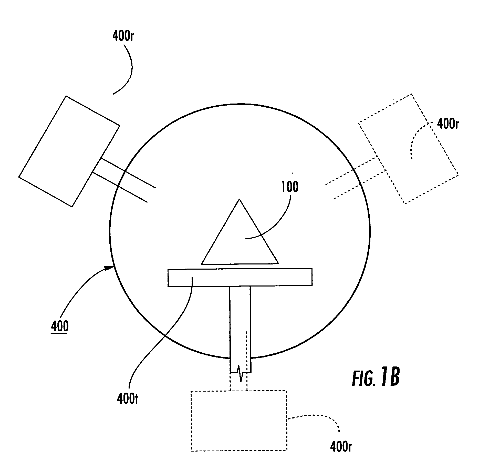
The present invention provides a three-dimensional phantom assembly for use with a radiation treatment device. The phantom assembly includes a support member that holds a radiation sensitive media that is positioned between two opposed surfaces of the support member. The support member can releasably hold a dosimeter sheet that includes a reference indicia. The phantom assembly can be used to determine the isocenter location of the radiation treatment device by irradiating the radiation sensitive media with a first and second beam trajectory that passes through the two surfaces. The intersection of the beam trajectories is determined to estimate the isocenter. The invention also includes methods of evaluating the isocenter location of the radiation treatment device by obtaining a plurality of two dimensional digital images of radiation patterns and electronically generating a three-dimensional visual representation of the radiation isocenter using data from the images. The isocenter is defined with respect to a reference coordinate system in the phantom device. The invention provides a useful tool for accurately positioning the radiation treatment device and ensuring the accuracy of the treatment plan.

Problems solved by technology

Although the radiation can reduce the amount of diseased tissue, it can also have a harmful effect on the healthy tissue surrounding the diseased tissue.

Method used


Image

  • Radiation isocenter measurement devices and methods and 3-D radiation isocenter visualization systems and related methods
  • Radiation isocenter measurement devices and methods and 3-D radiation isocenter visualization systems and related methods
  • Radiation isocenter measurement devices and methods and 3-D radiation isocenter visualization systems and related methods

Examples


Embodiment Construction

[0043]The present invention will now be described more fully hereinafter with reference to the accompanying figures, in which embodiments of the invention are shown. This invention may, however, be embodied in many different forms and should not be construed as limited to the embodiments set forth herein. Like numbers refer to like elements throughout. In the figures, certain layers, components or features may be exaggerated for clarity, and broken lines illustrate optional features or operations, unless specified otherwise. In addition, the sequence of operations (or steps) is not limited to the order presented in the claims unless specifically indicated otherwise. Where used, the terms “attached”, “connected”, “contacting”, “coupling” and the like, can mean either directly or indirectly, unless stated otherwise.

[0044]As used herein, the singular forms “a”, “an” and “the” are intended to include the plural forms as well, unless the context clearly indicates otherwise. It will be fu...


PUM


Abstract

A three-dimensional phantom assembly for use with a radiation treatment device includes a three-dimensional support member having at least two, spaced apart opposed surfaces configured to hold at least one generally planar radiation sensitive dosimeter sheet such that the dosimeter sheet generally conforms to a shape defined by the two opposed surfaces. During irradiation, a radiation beam trajectory passes through the two opposed surfaces. Related systems methods for determining a radiation isocenter and / or generating a 3-D visualization of the radiation isocenter using radiation patterns obtained using a phantom are also described.

Description

RELATED APPLICATIONS[0001]This application claims the benefit of priority to U.S. Provisional Patent Application Ser. No. 60 / 584,670 filed Jul. 1, 2004, the contents of which are hereby incorporated by reference as if recited in full herein.FIELD OF THE INVENTION[0002]The present invention relates to methods and devices for measuring distances to a subject for therapies employing radiation.BACKGROUND OF THE INVENTION[0003]Patients undergoing radiation therapy are typically placed on a treatment platform of a radiation treatment gantry. The gantry has a radiation source that is used to generate a radiation beam that irradiates a region of interest in the patient, such as diseased tissue including a tumor or cancerous growth site. Although the radiation can reduce the amount of diseased tissue, it can also have a harmful effect on the healthy tissue surrounding the diseased tissue. Thus, it is generally desirable to deliver the lowest effective dose of radiation localized with respect...

Claims


Application Information

Patent Timeline
Patent Type & Authority Patents(United States)
IPC IPC(8): A61N5/10
CPCA61N5/1048A61B6/583A61N2005/1076
Inventor JENKINS, TODD PERRINALLISON, RON RUSSELLSIBATA, CLAUDIO
Owner EAST CAROLINA UNIVERISTY
Learn More