Magnetic recording media and method of forming them
a recording media and magnetic field technology, applied in the field of magnetic recording media, can solve the problems of high saturation flux density, inability to increase the density infinitely, and general corrosion resistance, and achieve the effect of steady distribution of the magnetic field of the recording media
- Summary
- Abstract
- Description
- Claims
- Application Information
AI Technical Summary
Benefits of technology
Problems solved by technology
Method used
Image
Examples
example 1
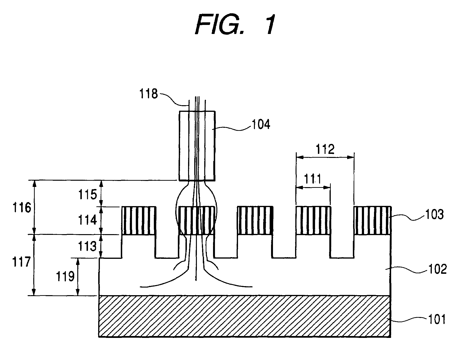
[0042]FIG. 1 is a cross sectional view schematically showing the perpendicular magnetic recording media according to one embodiment of the present invention. As shown in the sectional view of FIG. 1, the magnetic recording media has a structure in which various layers such as a foundation layer and a magnetic layer are formed on a circular shaped disk substrate. On the surface of the recording media, track patterns including a servo region and a data region are formed concentrically. In FIG. 1, a direction perpendicular to the sheet face, direction A, indicates a track running direction, and the direction parallel to the sheet face, direction B, indicates a track width direction. In other words, a magnetic head 104 proceeds along the direction A, with respect to the sheet face. The magnetic head 104 floats, with maintaining a predetermined flying height 115 with respect to the recording media.
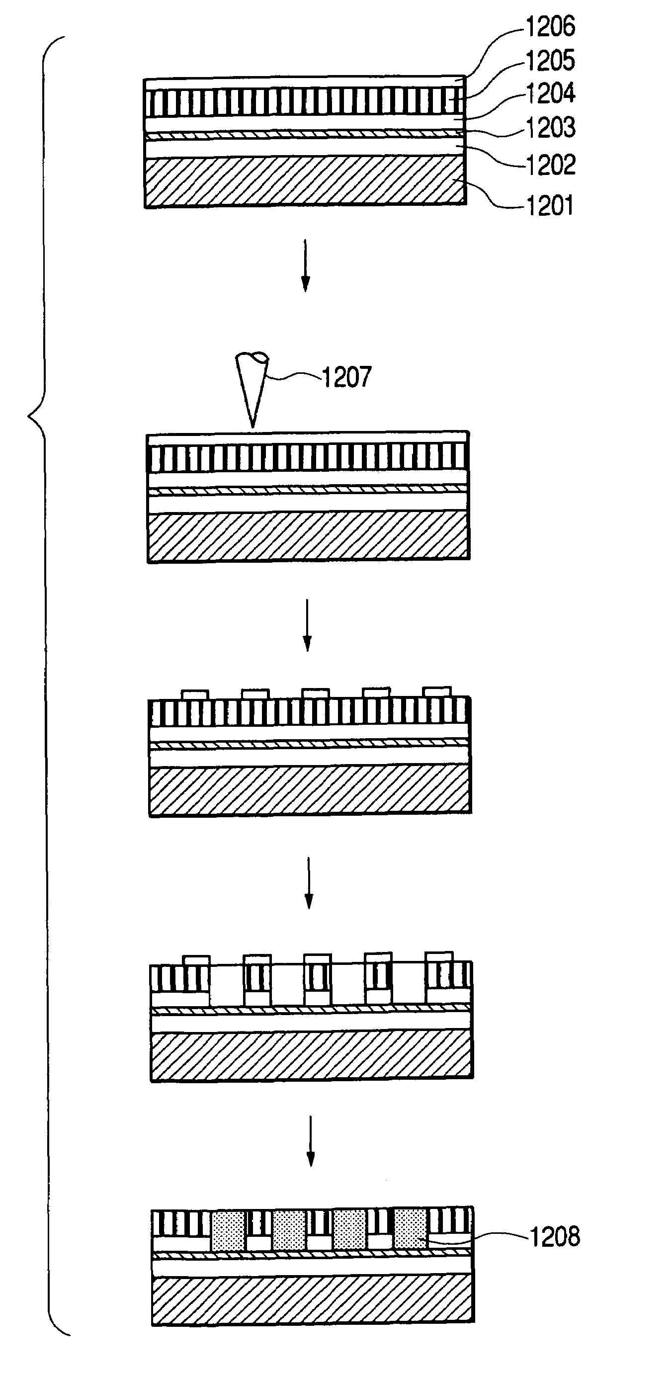
[0043]The perpendicular magnetic recording media of the present example is obtained by form...
example 2
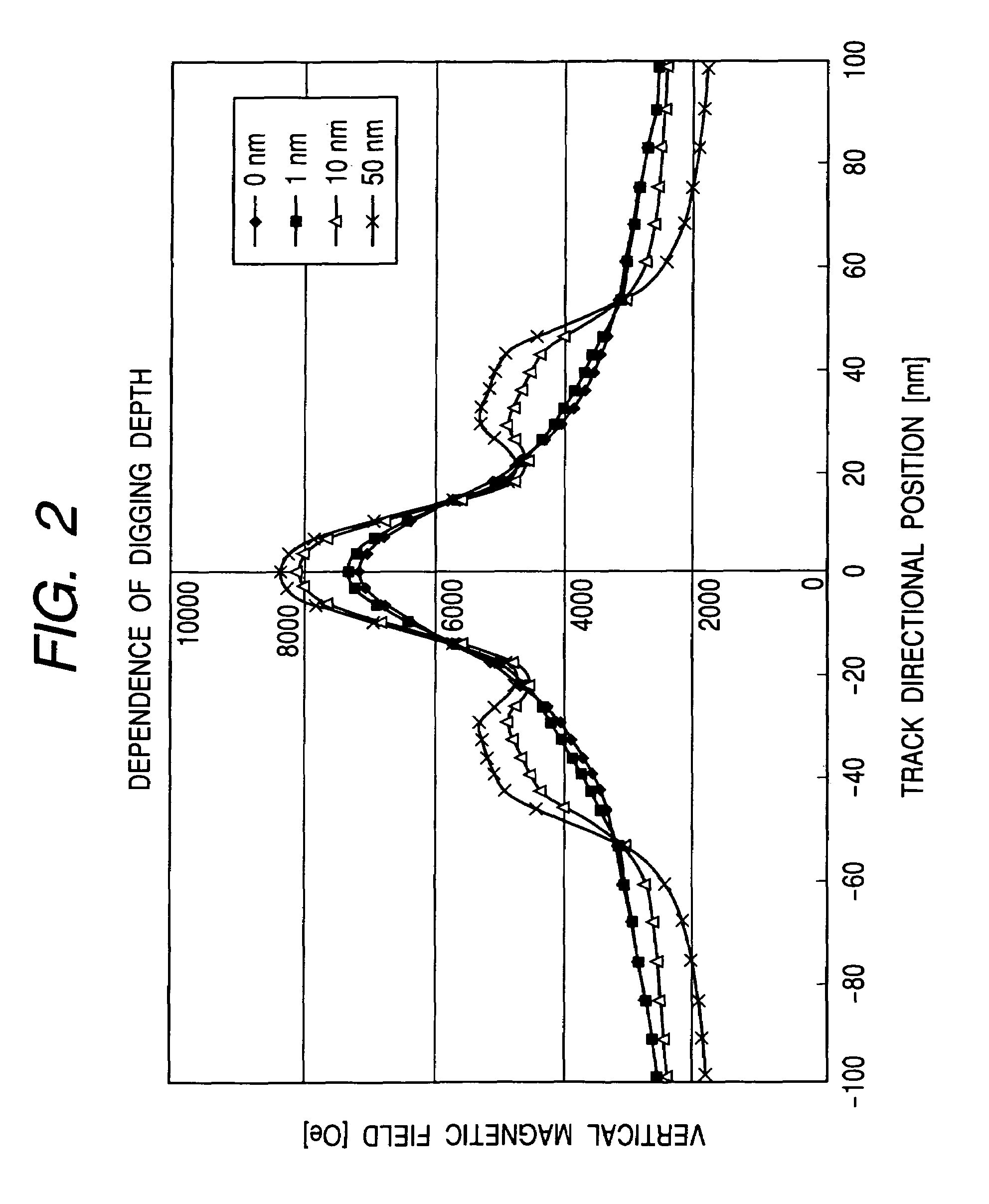
[0055]FIG. 2 shows a result of calculation, assuming the horizontal axis as a track directional position and the vertical axis as a vertical substance of the magnetic field generated by the SPT writer 104. In this calculation, the digging depth was changed under the condition that μ=1000, where μ indicates a relative permeability of the soft magnetic under layer 102, Bs=1.8 T, where Bs indicates a saturation flux density of the SPT writer, the distance 116 between the SPT head and the soft magnetic under layer=18 nm, the track pitch 112=36 nm, the width of magnet 111=20 nm, and magnetomotive force is 0.3 AT. Due to a computer power, the calculation range was limited to the region where the number of magnetic layers is 3×3. Further, since the magnetic permeability of the magnetic layer 103 was sufficiently small comparing to the relative permeability of the soft magnetic under layer 102 as described in the Example 1. Therefore, the effect of the magnetic permeability of the magnetic ...
example 3
[0058]FIG. 3 shows a result of calculation, assuming the horizontal axis as a digging depth and the vertical axis as the maximum magnetic field intensity in the perpendicular direction just below the SPT writer 104. In this calculation, the digging depth was changed under the condition that μ=2000, where μ indicates the relative permeability of the soft magnetic under layer 102, Bs=2.0 T, where Bs indicates the saturation flux density of the SPT writer, the distance 116 between the SPT head and the soft magnetic under layer=18 nm, the track pitch 112=36 nm, the width of magnet 111=20 nm, and magnetomotive force was 0.3 AT.
[0059]As in the case with Example 2, the calculation range was limited to the region where the number of the magnetic layers was 3×3, and the calculation was carried out, ignoring the effect of the magnetic layer 103. It has been found that the intensity of the magnetic field perpendicular substance became higher by increasing the digging depth amount 113 from zero...
PUM
| Property | Measurement | Unit |
|---|---|---|
| width | aaaaa | aaaaa |
| width | aaaaa | aaaaa |
| width | aaaaa | aaaaa |
Abstract
Description
Claims
Application Information
 - R&D
- Intellectual Property
- Life Sciences
- Materials
- Tech Scout
- Unparalleled Data Quality
- Higher Quality Content
- 60% Fewer Hallucinations
Browse by: Latest US Patents, China's latest patents, Technical Efficacy Thesaurus, Application Domain, Technology Topic, Popular Technical Reports.
© 2025 PatSnap. All rights reserved.Legal|Privacy policy|Modern Slavery Act Transparency Statement|Sitemap|About US| Contact US: help@patsnap.com


