Magnetic recording media and method of forming them

a recording media and magnetic field technology, applied in mechanical recording, recording information storage, instruments, etc., can solve the problems of high saturation flux density, general corrosion resistance, etc., and achieve the effect of steady distribution of the recording magnetic field

Inactive Publication Date: 2006-08-29
HITACHI LTD
View PDF18 Cites 30 Cited by
  • Summary
  • Abstract
  • Description
  • Claims
  • Application Information

AI Technical Summary

Benefits of technology

[0019]The present invention provides a means for solving a problem that it is difficult to carry out a magnetic recording onto a recording bit made of a magnetic material having a la

Problems solved by technology

In order to increase the saturation flux density, various materials have been developed, but it is impossible to increase the density infinitely.
Further, it is known that a material with a high saturation flux density, currently under development, generally has a problem in corrosion resistance.
Therefore, as the uniaxial-magnetic anisotropy constant (Ku) of a recording media increases, it i

Method used


Image

  • Magnetic recording media and method of forming them
  • Magnetic recording media and method of forming them
  • Magnetic recording media and method of forming them

Examples


example 1

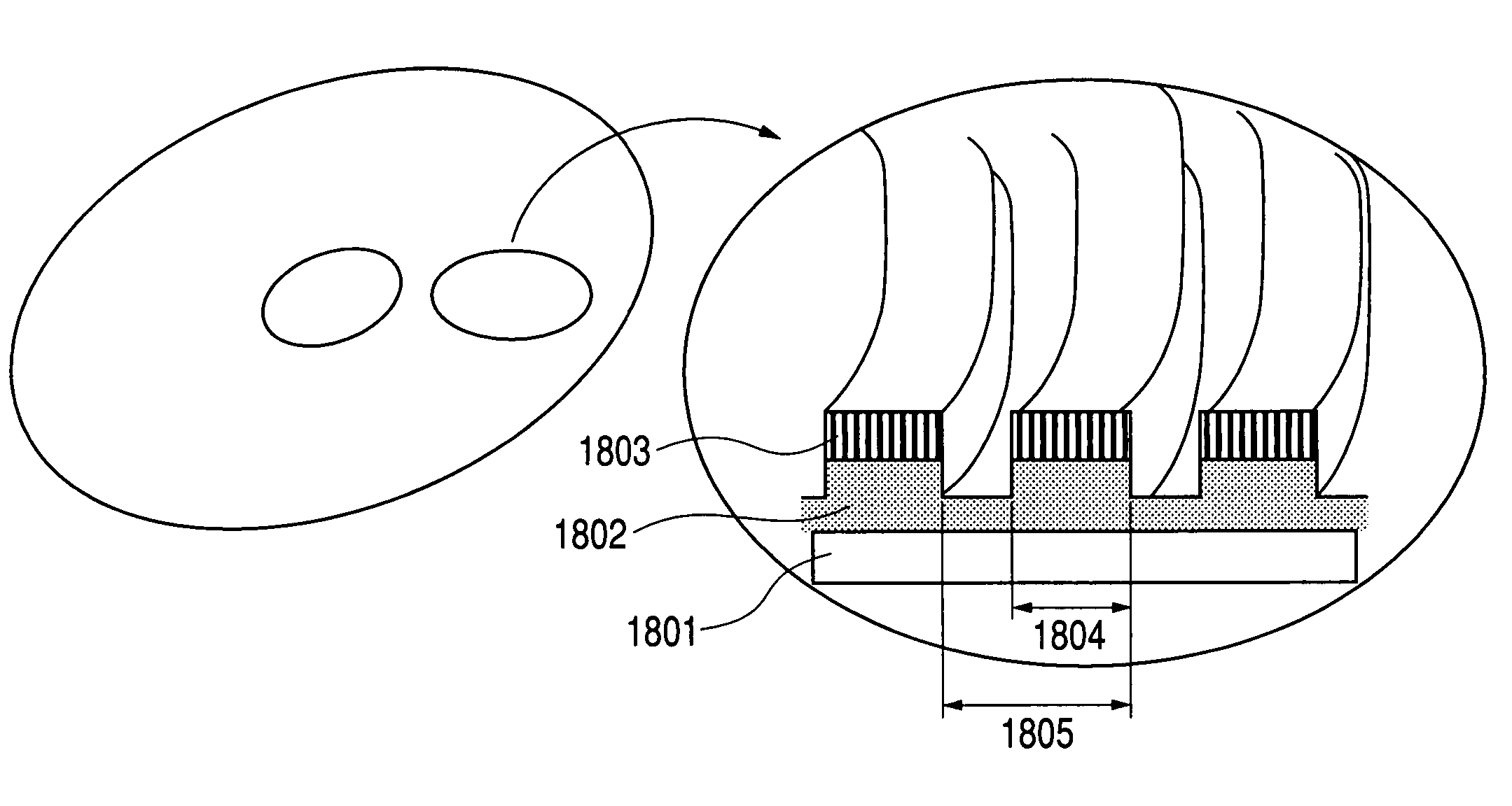
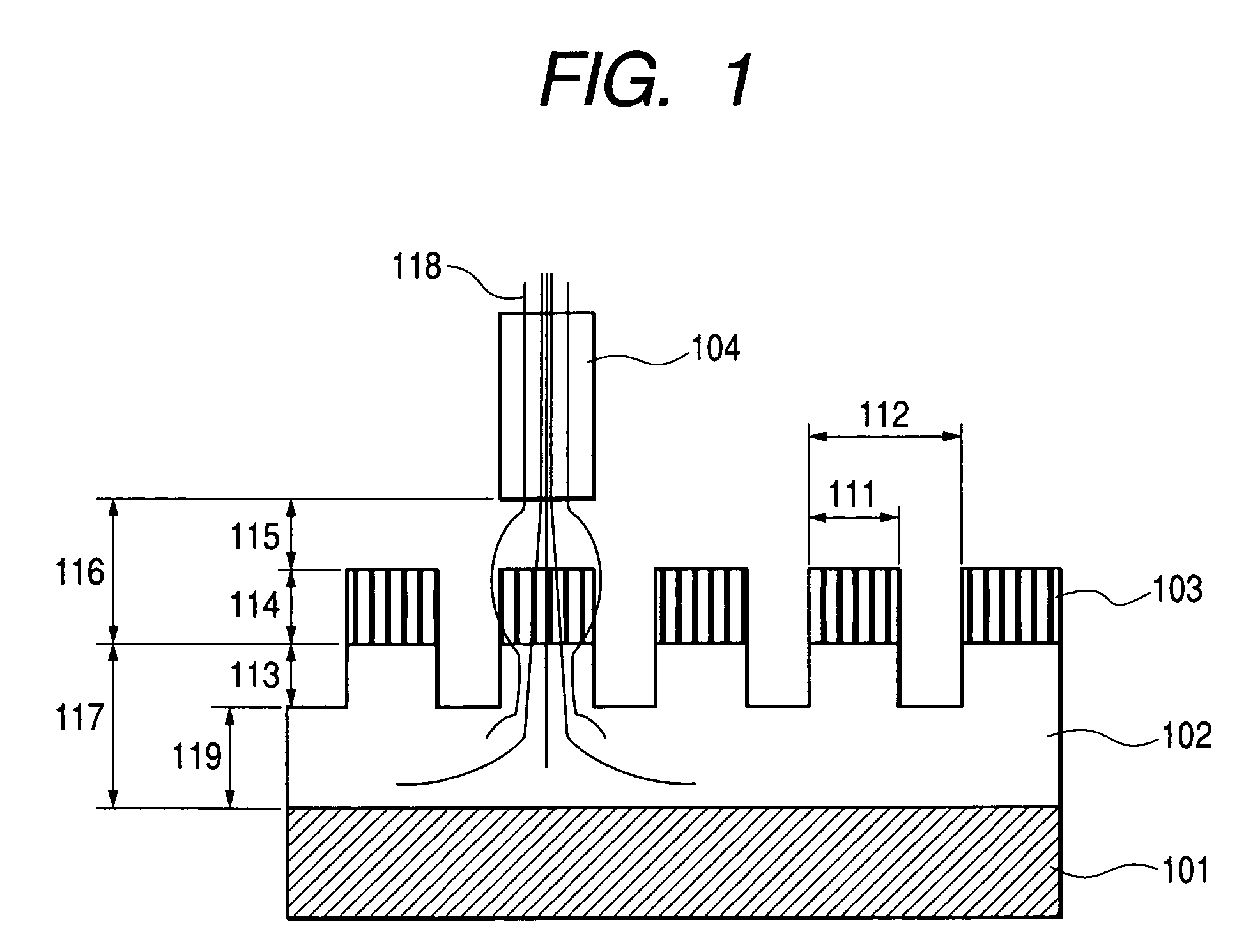
[0042]FIG. 1 is a cross sectional view schematically showing the perpendicular magnetic recording media according to one embodiment of the present invention. As shown in the sectional view of FIG. 1, the magnetic recording media has a structure in which various layers such as a foundation layer and a magnetic layer are formed on a circular shaped disk substrate. On the surface of the recording media, track patterns including a servo region and a data region are formed concentrically. In FIG. 1, a direction perpendicular to the sheet face, direction A, indicates a track running direction, and the direction-parallel to the sheet face, direction B, indicates a track width direction. In other words, a magnetic head 104 proceeds along the direction A, with respect to the sheet face. The magnetic head 104 floats, with maintaining a predetermined flying height 115 with respect to the recording media.

[0043]The perpendicular magnetic recording media of the present example is obtained by form...

example 2

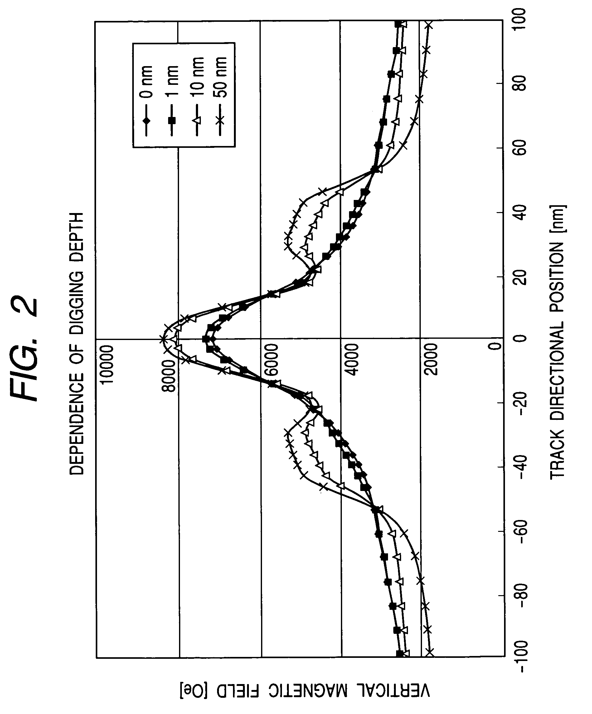
[0055]FIG. 2 shows a result of calculation, assuming the horizontal axis as a track directional position and the vertical axis as a vertical substance of the magnetic field generated by the SPT writer 104. In this calculation, the digging depth was changed under the condition that i=1000, where i indicates a relative permeability of the soft magnetic under layer 102, Bs=1.8 T, where Bs indicates a saturation flux density of the SPT writer, the distance 116 between the SPT headland the soft magnetic under layer=18 nm, the track pitch 112=36 nm, the width of magnet 111=20 nm, and magnetomotive force is 0.3 AT. Due to a computer power, the calculation range was limited to the region where the number of magnetic layers is 3×3. Further, since the magnetic permeability of the magnetic layer 103 was sufficiently small comparing to the relative permeability of the soft magnetic under layer 102 as described in the Example 1. Therefore, the effect of the magnetic permeability of the magnetic ...

example 3

[0058]FIG. 3 shows a result of calculation, assuming the horizontal axis as a digging depth and the vertical axis as the maximum magnetic field intensity in the perpendicular direction just below the SPT writer 104. In this calculation, the digging depth was changed under the condition that i=2000, where i indicates the relative permeability of the soft magnetic under layer 102, Bs=2.0 T, where Bs indicates the saturation flux density of the SPT writer, the distance 116 between the SPT head and the soft magnetic under layer=18 nm, the track pitch 112=36 nm, the width of magnet 111=20 nm, and magnetomotive force was 0.3 AT.

[0059]As in the case with Example 2, the calculation range was limited to the region where the number of the magnetic layers was 3×3, and the calculation was carried out, ignoring the effect of the magnetic layer 103. It has been found that the intensity of the magnetic field perpendicular substance became higher by increasing the digging depth amount 113 from zero...


PUM


Abstract

The present invention is directed to-carrying out a high density magnetic recording to a material having a large coercive force by perpendicular magnetic recording head.
By giving a patterning onto a soft magnetic under layer of a perpendicular two-layer recording media in sync with a period of a recording bit, a magnetic field from a write head can be allowed to converge to a soft magnetic column. Therefore, a magnetization reversal of the magnetic recording media material having a large anisotropic constant becomes possible, and then a high density magnetic recording can be achieved.

Description

BACKGROUND OF THE INVENTION[0001]1. Field of the Invention[0002]The present invention relates to a magnetic recording media, a magnetic recording system and a method of forming them.[0003]2. Discussion of the Background[0004]Recently, in a magnetic recording media, as a recording density is more enhanced, a more stable magnetization in recording against a thermal fluctuation is required. Therefore, there is a tendency that the uniaxial magnetic anisotropy constant (Ku) of a magnetic material is increasing, which is used as a material of a magnetic layer responsible for recording. A large recording magnetic field is required so as to carry out recording on the magnetic layer having a large Ku. Consequently, a study has been conducted as to a write head which generates the recording magnetic field, from both structural and material viewpoints. In the meantime, there has been suggested a perpendicular recording method where two-layer perpendicular media provided with a soft magnetic un...

Claims


Application Information

Patent Timeline
IPC IPC(8): G11B5/65G11B5/17G11B7/20G11B5/667G11B5/73G11B5/84G11B5/855
CPCG11B5/667G11B5/855G11B5/8404G11B5/82
Inventor HAGINOYA, CHISEKISUZUKI, KAORIKIMURA, HISASHIFUTAMOTO, MASAAKIMATSUYAMA, HIDEO
Owner HITACHI LTD
Why Eureka
Try Eureka