Method of producing anti-reflection film

a technology of anti-reflection film and film layer, which is applied in the direction of instruments, natural mineral layered products, transportation and packaging, etc., can solve the problem of difficulty in accurately calculating the characteristic matrix

Inactive Publication Date: 2008-04-01
BRIDGESTONE CORP
View PDF11 Cites 21 Cited by
  • Summary
  • Abstract
  • Description
  • Claims
  • Application Information

AI Technical Summary

Problems solved by technology

However, it is difficult to accurately calculate the characteristic matrix due to the complicated characteristic matrices and to obtain an optimum value.

Method used


Image

  • Method of producing anti-reflection film
  • Method of producing anti-reflection film
  • Method of producing anti-reflection film

Examples


example 1

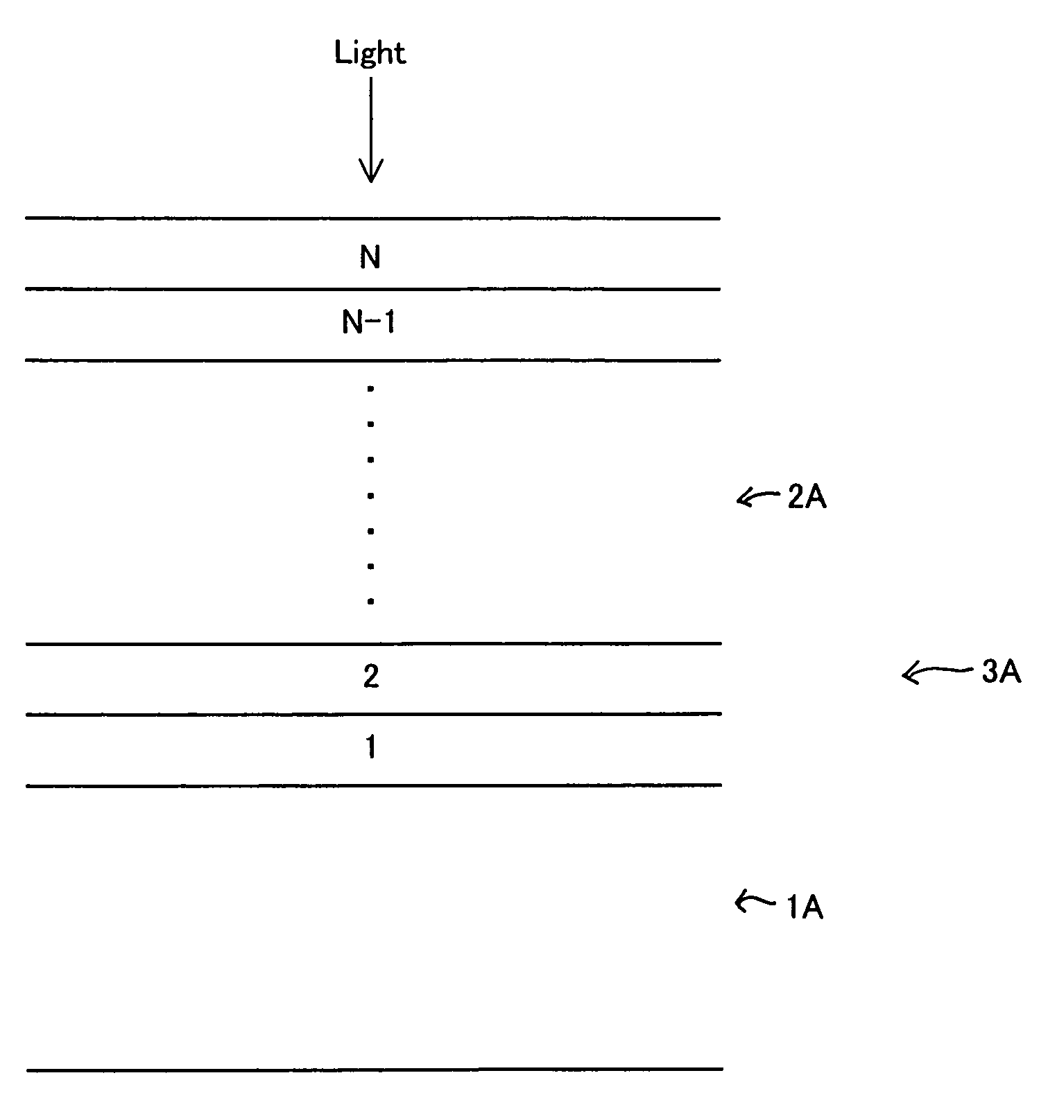
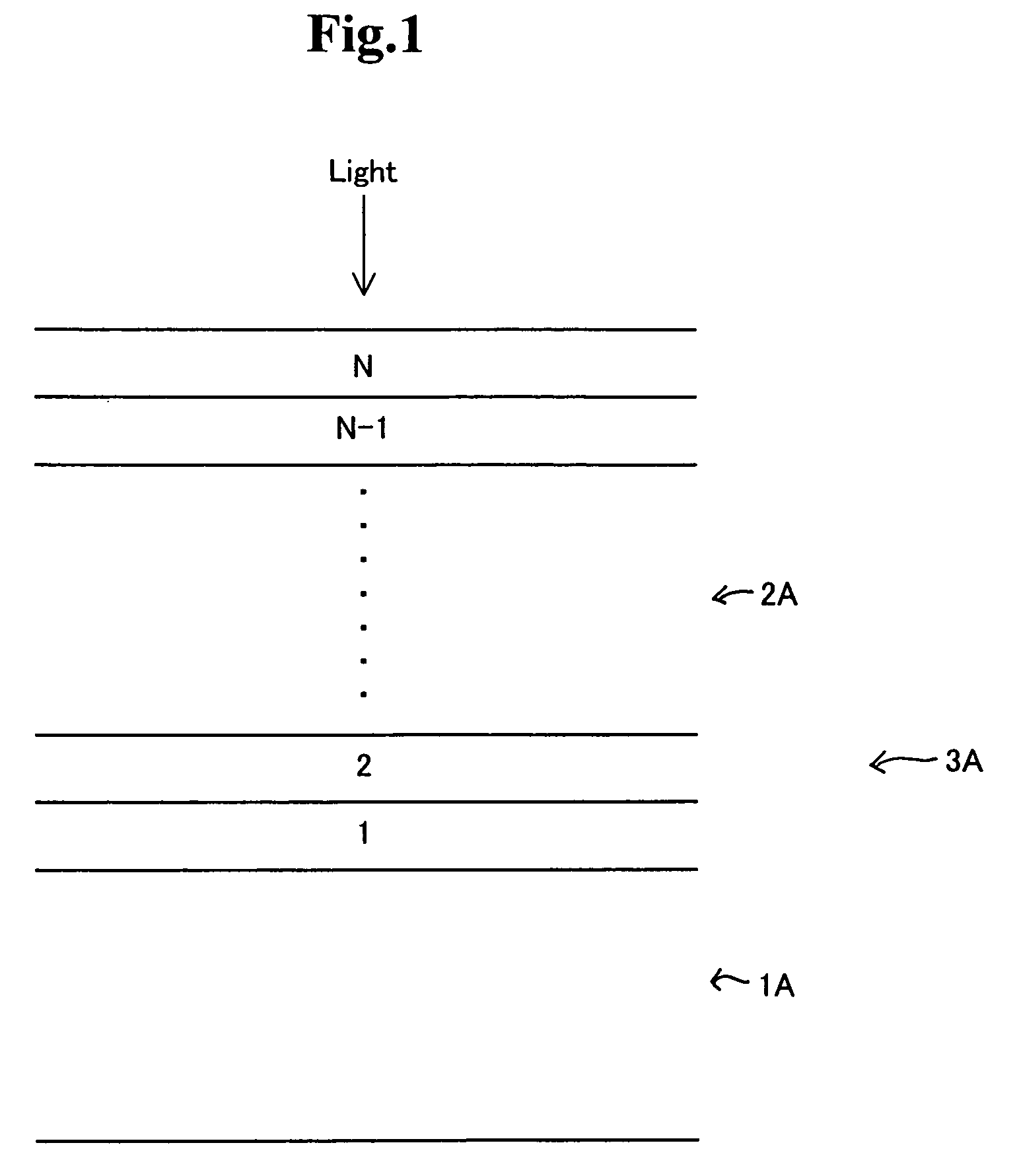
[0071]A PET film with a thickness of 188 μm was used as the transparent substrate. The PET film had an attenuation coefficient of zero and a reflective index of 1.65. A hard coat material Z7501 commercially available from Nihon Synthetic Rubber Co. was coated on the transparent substrate to form a hard coat layer with a thickness of 5 μm. The hard coat layer had an attenuation coefficient of zero and a refractive index of about 1.5. Ag was deposited on the hard coat layer by sputtering to form a thin layer (next layer) with a thickness of 3.6 nm. The Ag layer had an attenuation coefficient of zero and a reflective index of 0.101. A mixture of a polyfunctional acrylic resin and silica was coated on the Ag layer by photogravure, and the coated layer was cured by UV irradiation after drying to form an outermost layer with a thickness of 50 nm. The outermost layer had an attenuation coefficient of zero and a refractive index of 1.51. The optical admittance Y at the interface between the...

example 2

[0075]An anti-reflection film was manufactured by the same method as in Example 1, except that Au was deposited by sputtering to form a layer (next layer) with a thickness of 5.9 nm, and the outermost layer had a thickness of 54 nm. The Au layer had an attenuation coefficient of zero and a reflective index of 0.35. The optical admittance Y at the interface between the outermost layer and the Au layer was calculated as follows:

Y=x+iy=1.57−0.64i

[0076]It was found that the anti-reflection film has the reflectivity of 0.0% at a wavelength of 550 nm. The values of A and B obtained by the same calculations in Example 1 are shown in Table 1.


PUM

PropertyMeasurementUnit
thicknessaaaaaaaaaa
thicknessaaaaaaaaaa
thicknessaaaaaaaaaa

Abstract

A method of producing an anti-reflection film includes forming a first layer on a transparent substrate, forming a second layer on the first layer, and forming the third layer on the second layer. When an optical admittance Y at a surface of the second layer is represented by,Y=HE=(x+iy)where i is the imaginary number unit,thicknesses and reflective indexes of the substrate, first layer, second layer, and third layer are selected so that x and y satisfy the following formula,0.9x{(n2−n02) / 2n0}2<{x−(n2+n02) / 2n0}2+y2<1.1x{(n2−n02) / 2n0}2 where n is a refractive index of the third layer and n0 is a refractive index of an outer region at an outside of the anti-reflection film.

Description

CROSS REFERENCE TO RELATED APPLICATION[0001]This is a continuation-in-part application of a patent application Ser. No. 10 / 267,747 filed on Oct. 10, 2002 now abandoned.BACKGROUND OF THE INVENTION AND RELATED ART STATEMENT[0002]The present invention relates to a method of producing an anti-reflection film with a desired reflectivity used for a display such as a CRT (cathode ray tube) screen and a PDP (plasma display panel) screen.[0003]An anti-reflection film is generally formed of a plurality of layers having alternately laminated low-reflectivity layers and high-reflectivity layers on a transparent synthetic resin sheet. The anti-reflection film is attached to a CRT screen or a PDP screen with a transparent adhesive (including a self-attaching adhesive). When such an anti-reflection film is attached to the PDP or CRT, the synthetic resin sheet faces outside (side away from the CRT or PDP, or side exposed to the atmosphere).[0004]In order to calculate reflectivity and transmittance ...

Claims


Application Information

Patent Timeline
Patent Type & Authority Patents(United States)
IPC IPC(8): B05D5/06G02B1/11
CPCG02B1/115G02B1/116Y10T428/24942Y10T428/259Y10T428/256G02B1/16
Inventor NISHIDA, MITSUHIROKUSANO, YUKIHIROKATO, NOBUKO
Owner BRIDGESTONE CORP
Why Eureka
Try Eureka